Articles in the Positioning Category


This paper investigates the quality of positioning results from AUSPOS when the observation data is submitted individually versus when submitted as a cluster of several concurrently observed survey marks.
Nicholas Gowans
Geodetic Surveyor in the Geodetic Operations team at DCS Spatial Services, NSW Department of Customer Service, in Bathurst, Australia
Dr Volker Janssen
Senior Technical Surveyor in the Geodetic …

Precise Point Positioning (PPP) is a versatile tool that has drawn attention among researchers in processing static and kinematic…

Navigation often relies on high accuracy and high-update rate global navigation satellite systems (GNSS) such as GPS, Galileo, Glonass, Beidu, Navstar…

Mass-market applications, ranging from self-driving cars, unmanned aerial vehicles (UAV) to handheld smartphones, are increasingly demanding high-precision from GNSS integrated with other enabling navigation sensors…

The capability to monitor the gathering of crowds in restricted geographic areas is a key enabler for the development of safety and security measures…

Along with the evolution of mobile devices a wide landscape of applications tailored for mobile usage has been developed…

Contemporary navigation systems heavily rely on the satellite based systems, mostly still on GPS. The systems proved robust and accurate enough for the vast majority of its today uses. However, there are situations where the reliability and the accuracy of such systems do not meet the expected criteria…
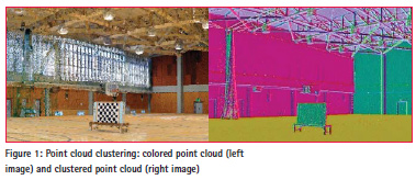
Massive point cloud acquisition is an effective approach for 3D modeling of unknown objects in an indoor environment.

Introduction contains sections of status about the GNSS satellites, back ground of GNSS–based positioning methods, Threats in positioning and description of faults.

Indoor positioning is highly desired for many applications, including personnel tracking for safety in normally unmanned locations. There are several methods and technologies available to…


 (5.00 out of 5)