| Surveying | |
MyRTKnet: Get set and go!
|
||||
| The Department of Survey and Mapping Malaysia (JUPEM) is the competent authority in providing both horizontal and vertical survey control to the surveying community in Malaysia. This is carried out through the setting up of a surveying infrastructure throughout the country for the eventual purpose of national development, security and defence. In line with the government’s endeavour to improve its delivery mechanism, there have been many initiatives made by JUPEM. One of them is the effort made to use real-time survey technology for the enhancement of its many services and dissemination of various geodetic products rendered by the department.
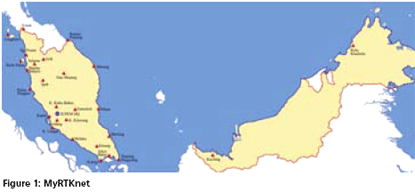
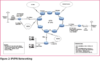
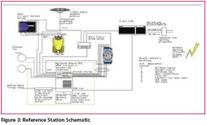
From 1997 to 2000, JUPEM has set up a permanent GPS network known Presently, MASS provides an excellent frame of reference for geodetic positioning in Malaysia, and several kinematic applications have been carried out by post-processing thedata. However, the possibility of having realtime access to the data observed by the GPS network would dramatically and clearly increase its synergy with land surveying activities. For instance, it would allow the use of GPS for centimeter positioning over the entire territory of Malaysia through the broadcasting of RTK corrections. Existing ScenarioReal-Time Kinematic (RTK) is now widely used for surveying and other precise positioning applications. The classical RTK technique requires that GPS data be transmitted from a single base receiver to one or more roving units. RTK can provide centimeter position accuracy, but the accuracy and reliability of the standard RTK solution decreases with increasing distance from the Base Station. This limitation on the distance between the roving GPS receiver and the RTK Base Station is due to the systematic effects of ephemeris, tropospheric and ionospheric errors. These systematic errors result in reduced accuracy and increasing initialization time as the distance between base and rover increases. Besides the aforementioned constraint, the limitation is also due to the range of available radio telemetry solutions. In practice, this means that a temporary RTK Base Station must be established close to the work area, often at a location that does not provide any physical security or continuous power supply. Each time such a temporary reference station is established, there is a likelihood of introducing an error in the reference station coordinates that will be transferred into the position calculated by the rover RTK receiver. Such an error can easily go undetectedwhen using a single base station. ObjectivesIn order to take full advantage of the real-time capabilities of the RTK network, MyRTKnet has been designed with the following objectives: i. To establish a network of permanently running GPS base stations, at a spacing of 30 to 150 km, feeding GPS data to a processing centre via frame-relay IPVPN communication network. ii. To establish a central facility that will model the spatial errors which limit GPS accuracy through a network solution and generate corrections for roving receivers positioned anywhere inside the network with an accuracy better than a few centimeters (dense network) to a few decimeters (sparse network) in real time. iii. To establish a web site that will make available near real time (1 – 3 Network designObjectivesThe primary goals in designing the system were for efficient and easy operations, facilitate user understanding of the network and for expandability. Some empirical numerical limits have been suggested for IP addressing and efficient operation of the system. The networking protocol used is the Internet Protocol (IP). Though contained in a single private network, the system was split into 2 subnets which is not representative of classical IP subnet class. As such this network is considered as ‘classless’. Each subnet consists of all reference stations and the Control Center (also referred to as central control or CC). Malaysia Real Time Kinematic GPS Network (MyRTKnet)The RTK Network Solution concept is based on having a network of twenty-seven (27) GPS reference stations continuously connected via IP VPN to a Control Centre (Figure 1). The computer processor at the Control Centre continuously gathers the information from all GPS receivers, and creates a living database of Regional Area Corrections. Physical CommunicationsThe physical communications infrastructure is provided by the IPVPN over COINS frame relay system. This system works by connecting any respective site into the Telekoms Malaysia frame relay network. The service is available throughout Malaysia except for some isolated locations. The advantage of using IPVPN verses point to point leased lines is that IPVPN will require only a single high speed connection and modem at the Central Control rather than a connection comprising of a modem and separate leased line for each station. A schematic representation of the system communications is shown in Figure 2 Reference stationsPhysical EnclosureThe physical enclosure for the equipment at each site is a small structure or allocated room of approximately 3m x 4m. This room is being cooled by 2 air conditioners that alternate during the day such that the total time that any one unit is on over the entire day is 12 hours. System SchematicThe system schematic for the reference stations are shown in Figure 3. The system is designed for autonomous operation and is able to run for 48 hours without power. |
||||


 (No Ratings Yet)


