| Surveying | |
MyRTKnet: Get set and go!
|
||||
| The Department of Survey and Mapping Malaysia (JUPEM) is the competent authority in providing both horizontal and vertical survey control to the surveying community in Malaysia. This is carried out through the setting up of a surveying infrastructure throughout the country for the eventual purpose of national development, security and defence. In line with the government’s endeavour to improve its delivery mechanism, there have been many initiatives made by JUPEM. One of them is the effort made to use real-time survey technology for the enhancement of its many services and dissemination of various geodetic products rendered by the department.
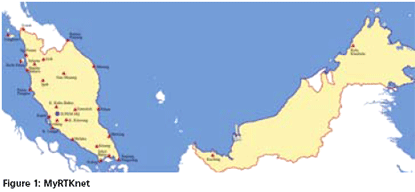
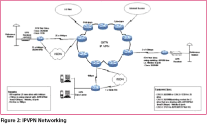
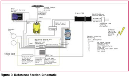
From 1997 to 2000, JUPEM has set up a permanent GPS network known Presently, MASS provides an excellent frame of reference for geodetic positioning in Malaysia, and several kinematic applications have been carried out by post-processing thedata. However, the possibility of having realtime access to the data observed by the GPS network would dramatically and clearly increase its synergy with land surveying activities. For instance, it would allow the use of GPS for centimeter positioning over the entire territory of Malaysia through the broadcasting of RTK corrections. Existing ScenarioReal-Time Kinematic (RTK) is now widely used for surveying and other precise positioning applications. The classical RTK technique requires that GPS data be transmitted from a single base receiver to one or more roving units. RTK can provide centimeter position accuracy, but the accuracy and reliability of the standard RTK solution decreases with increasing distance from the Base Station. This limitation on the distance between the roving GPS receiver and the RTK Base Station is due to the systematic effects of ephemeris, tropospheric and ionospheric errors. These systematic errors result in reduced accuracy and increasing initialization time as the distance between base and rover increases. Besides the aforementioned constraint, the limitation is also due to the range of available radio telemetry solutions. In practice, this means that a temporary RTK Base Station must be established close to the work area, often at a location that does not provide any physical security or continuous power supply. Each time such a temporary reference station is established, there is a likelihood of introducing an error in the reference station coordinates that will be transferred into the position calculated by the rover RTK receiver. Such an error can easily go undetectedwhen using a single base station. ObjectivesIn order to take full advantage of the real-time capabilities of the RTK network, MyRTKnet has been designed with the following objectives: i. To establish a network of permanently running GPS base stations, at a spacing of 30 to 150 km, feeding GPS data to a processing centre via frame-relay IPVPN communication network. ii. To establish a central facility that will model the spatial errors which limit GPS accuracy through a network solution and generate corrections for roving receivers positioned anywhere inside the network with an accuracy better than a few centimeters (dense network) to a few decimeters (sparse network) in real time. iii. To establish a web site that will make available near real time (1 – 3 Network designObjectivesThe primary goals in designing the system were for efficient and easy operations, facilitate user understanding of the network and for expandability. Some empirical numerical limits have been suggested for IP addressing and efficient operation of the system. The networking protocol used is the Internet Protocol (IP). Though contained in a single private network, the system was split into 2 subnets which is not representative of classical IP subnet class. As such this network is considered as ‘classless’. Each subnet consists of all reference stations and the Control Center (also referred to as central control or CC). Malaysia Real Time Kinematic GPS Network (MyRTKnet)The RTK Network Solution concept is based on having a network of twenty-seven (27) GPS reference stations continuously connected via IP VPN to a Control Centre (Figure 1). The computer processor at the Control Centre continuously gathers the information from all GPS receivers, and creates a living database of Regional Area Corrections. Physical CommunicationsThe physical communications infrastructure is provided by the IPVPN over COINS frame relay system. This system works by connecting any respective site into the Telekoms Malaysia frame relay network. The service is available throughout Malaysia except for some isolated locations. The advantage of using IPVPN verses point to point leased lines is that IPVPN will require only a single high speed connection and modem at the Central Control rather than a connection comprising of a modem and separate leased line for each station. A schematic representation of the system communications is shown in Figure 2 Reference stationsPhysical EnclosureThe physical enclosure for the equipment at each site is a small structure or allocated room of approximately 3m x 4m. This room is being cooled by 2 air conditioners that alternate during the day such that the total time that any one unit is on over the entire day is 12 hours. System SchematicThe system schematic for the reference stations are shown in Figure 3. The system is designed for autonomous operation and is able to run for 48 hours without power. |
||||
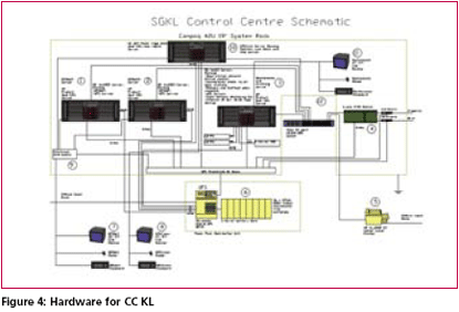
Central Control KLHardwareThe hardware for the CC KL configuration is shown in Figure 4. The Control Centre consists of the following: Computer systemsThe system comprises 3 HP Proliant servers and a single rack mount router computer, GPStream server. Each of these computers and their respective function are discussed below. GPSNet serversThe VRS computers are server grade HP Proliant computers configured in a pure ‘hot standby’ mode and are designated as VRS primary and VRS secondary, GPSNet1 and GPSNet2 respectively. Each of the servers is on line with the VRS application running. Both servers receive data from all the reference stations, logging these RINEX data and deliver RTKnet corrections when connected. However, it is the function of the GPStream server to distribute the reference station receiver data to the GPSNet servers and controls which server get user requests for RTKnet or DGPSnet corrections. Since both servers are online, should GPSNet1 server fail to operate, any online field user receiving RTKnet or DGPSnet corrections will lose their connection and the line will hang up. As soon as the field user calls back in, the GPStream server will detect the failure of the GPSNet1 server and will pass the request from the user to GPSNet2 server. Since both servers would be continuously logging data, none of the logged RINEX data would be affected. VRS router Computer – GPStream ServerThe GPStream Server has two functions: User requests for RTKnet or DGPSnet The GPStream server is essential for the operations of the system; so it is built in a dual power supply rack mount chassis and uses RAID hot swap hard disks so as to minimize possibilities of failure. Maintenance and Archiving ServerThe maintenance and archiving server is used for archiving RINEX and alarm data to CD and for monitoring the physical status of the reference stations. An application running on the archiving machine will check the reference station status every 5 minutes. Also on this machine is an application that make at every second to check which users are logged onto the system. This data is logged so that phone billing records may be cross checked. All computers are located in a 42U 19” rack with the GPSNet servers and the GPStream server sharing a monitor, keyboard and mouse via a KVM switch and the archiving/maintenance server having its own monitor, keyboard and mouse. All monitors, mice and keyboards are located at work table near the rack. Telnet access to the routers and remote sites are done from here. Virtual Reference StationReference Station ConnectionsThe Trimble 5700 has its serial ports 1 and 3 connected to the MOXA’s Terminal Server (TS) serial ports 1 and 2. The MOXA’s TS serial ports behave like TCP ports. MOXA TS serial port 1 is assigned TCP port 4001 and port 2 TCP port 4002. Both TCP/IP sockets that are connected to the GPS receiver’s serial ports are configured in ‘server’ mode which means they are waiting for connections from a socket client. The GPStream server is configured to connect to the reference stations in socket client mode. This connection will initialize the receiver and start the RT17 data stream. It will then setup socket servers that can be connected to by the GPSNet servers to receive the streamed RT17 data. In this way both GPSNet servers will receive the data rather than only one. This connection will initialize the receiver and start the RT17 data stream. Remote User RTK or DGPS Call InGPSNet is configured in socket server mode for the RTKNet and DGPSNet modules. The remote user will use the registered Telco Mobile Phone Internet Connection through GSM or GPRS to access the Control Centre KL. When a call comes in, the router will authenticate the user before connecting to the system, by using the username and password. If it is in the authorization database, the connection is allowed to proceed, else the line is dropped. When the connection proceeds the router brings the line up and immediately connects to the appropriate socket on the GPStream server. The GPStream server then queries both of the available servers. If they both answer, the request is sent to GPSNet1 server. If only the secondary answers the request is then sent there. The GPStream server will continue to forward requests to and from the GPSNet servers. The field user is now connected and following the reception of a GGA NMEA string by the GPSNet server, GPSNet will begin sending RTK or DGPS corrections from a ‘virtual base’ whose coordinates are based from the field user submitted GGA string. Archiving/MonitoringUser accounting will be done from the archiving and maintenance server. An application will make query every second to check when users connect and disconnect to the server. The time the connection was initiatedand the time the connection was terminated will be logged to a file. Hot SwapThe system proposed runs the GPSNet servers in a ‘hot standby mode’ in which the secondary GPSNet2 server is up, connected to the reference stations and running VRS. The GPSNet2 server is also logging RINEX data along with the primary GPSNet1 server. The only thing that will happen when GPSNet1 sever fail is that the GPStream server will forward RTKnet and DGPSnet corrections’ requests to the GPSNet2 server. Thus, switching to the standby system will be done in seconds after the fault is confirmed rather than the 20-30 minutes with the clustering solution. MyRTKnet SERVICESVRS Correctiona) Within the limits of our MyRTKnet Dense Network, MyRTKnet provides VRS GPS corrections with an accuracy of 1 to 3 cm horizontally and 3 to 6 cm vertically. b) Distance dependent errors are considerably minimized with utilization of the MyRTknet network, thereby achieving increased accuracy and reliability. Static Correction Dataa) Within the larger limits of the Single Base Station Coverage, MyRTKnet Solutions provides data for post-processing of static survey sessions, enabling positioning in the order of 1 cm or even millimeter recovery limit. The data is provided in the standardized RINEX format and is available via our password protected internet website. b) Information with a data rate of 1- 15 seconds is stored indefinitely. c) Post-processing provides the highest accuracy and is suitable where increased precision is required. DGPS Correctiona) This application is a submeter Mapping and Navigation Technology. b) The service provided by MyRTKnet Solutions includes data for postprocessed positioning and Real Time Correction. Any receiver that is capable of Real Time Corrections and cell phone data service can be used to receive MyRTKnet Solutions’ Real Time RTCM corrections. c) Distance dependant errors are eliminated for users’ observations due to MyRTKnet Solutions’ array of base station locations. Hardware RequirementMyRTKnet Solutions correction can be applied to any mobile receiver capable of connecting to a data cell phone. Cell phone reception, therefore, is a requirement of the VRS correction service. Presently, there are mobile receivers which has both the capabilities of wireless connection to the cell phone and data collector. Any single or dual frequency GPS receiver can be used to collect data and for static correction data application, postprocessing software package is needed to reduce the data to final position that uses standard RINEX files. |
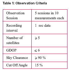
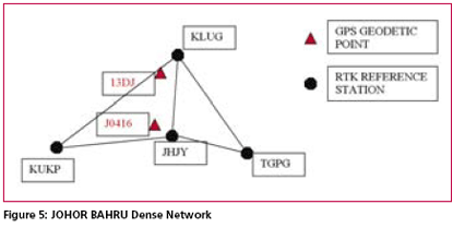
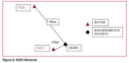
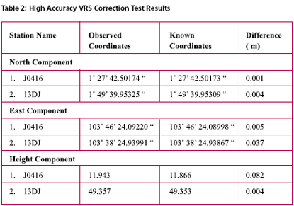
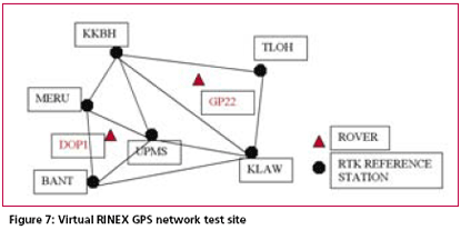
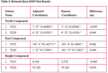
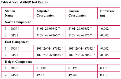
Possible Field ApplicationsMyRTKnet services can be used for various surveying applications ranging from setting up of control to the detailing of project sites; its usage will benefit surveyors and many other GPS users who rely on these utilities to locate their positions. The following are some of the possible field applications of MyRTKnet services: MyRTKnet testingCase study for high accuracy VRS correction testa. The objective of the High Accuracy VRS Correction Test is to compare GPS observed coordinates with their corresponding published GPS geodetic values. The test was carried out at the existing GPS geodetic network in the Dense Network. An example of the layout of the network test site is shown in Figure 5. b. The Dense Network consists of 3 sites located at Klang Valley, Penang and Johor Bahru. For this case study, Johor Bahru Dense Network was selected .This site comprises of four (4) GPS reference stations (known stations) namely KUKP, JHJY, TGPG and KLUG. The test was carried out using VRS technique with 5 sessions of observation (consisting of 10 measurements in each session) on 2 GPS receivers. c. Dual frequency GPS receivers were used in the test with the observation d. The final observed coordinates values as mentioned in table 2 were the results of the average of the whole set of observations. e. The results show that the accuracies in the horizontal and height component were less than 1 cm and 9 cm respectively. It also shows that for areas within 30 km from the network, the accuracies obtained were within the said levels. tableCase study for Network base DGPS correction test a. The objective of the Network Base DGPS Correction Test is to compare GPS observed coordinates with their corresponding published GPS geodetic values. The test was carried out at the existing GPS geodetic network in Peninsular Network. An example of the layout of the network test site is shown in Figure 6. b. The MARG (Marang) Reference Station in Terengganu is used for the test. The test was carried out using Network Base Differential GPS (DGPS) technique with 5 sessions of observation (consisting of 10 measurements in each session) on 2 GPS receivers. c. Two dual frequency GPS receivers were used in the test. The observation criteria applied was similar to the test (case study for high accuracy VRS correction test). d. The final observed coordinates values as mentioned in table 3 were the results of the average of the whole set of observations. e. The results show that the accuracies in the horizontal and height component were between 1 to 6 cm and 3 to 6 cm respectively. It also shows that for areas within 30 km from the network, the accuracies obtained were within the said levels. Case study for Virtual RINEX testa. The objective of the Virtual RINEX Data Test is to compare the GPS coordinates obtained from the processing of the Virtual RINEX data with their corresponding published GPS geodetic values. The test was carried out at the existing GPS geodetic network in Peninsular Network. An example of the layout of the network test site is shown in Figure 7. b. The Network site comprises of six (6) GPS reference stations (known stations) namely KKBH, MERU, UPMS, BANT, KLAW and TLOH. The test was carried out using GPS Static technique with 2 sessions of 10 minutes on 2 GPS receivers. c. Two dual frequency GPS receivers were used in the test. The observation criteria applied was similar to the test (case study for high accuracy VRS correction test). d. The comparison of the final adjusted coordinates and the published coordinates are as follows as mentioned in table 4. e. Results show that the accuracies in the horizontal and height component were between 1 to 2 cm and 10 cm respectively, and that for areas within 30 km from the network, the accuracies obtained were within the said levels. ConclusionThis paper introduces a new GPS positioning by way of RTK-GPS (VRS) using MyRTKnet services provided by DSMM. MyRTKnet has been successfully implemented with the establishment of a Network of Reference Stations equipped with GPS receiver, antenna, communication server/router, software, power supply, UPS, lightning arrestor and other accessories and equipments necessary for the full working of the station. A Control Centre has also been established equipped with computation server, software, power supply, UPS, communication router/server, Web server and other accessories and equipment necessary for the operations of the facility. The precision estimation of positioning results surveyed by VRS has also been verified. Outcome of field experiments shows that standard deviations of 3- components of real-time positioning by VRS are about ±2 cm in horizontal and less than ±4 cm in vertical and this meets the demand for survey precision of local control point. Network DGPS solutions have also been tested with results showing that sub-meter applications were possible in areas where VRS correction are not available. |
||||||||||||||||||||||||||||||||||||||
|
||||||||||||||||||||||||||||||||||||||
|



 (No Ratings Yet)


