| Navigation | |
The Implementation a Simulation Platform for INS/GNSS Integrated Systems
Readers may recall that in last issue we published the components of INS/GNSS simulation platform and principle of the simulator. Here we present the results and discussion. |
|
 |
|
||||
|
|||||
 |
|
||||
Results and Discussions
Some numerical examples are given in this section to illustrate the applicability and capability of proposed simulation platform. All the simulation scenarios are conducted with the specification of a tactical grade IMU with 0.0001g accelerometer bias and 0.75 deg/hr gyro drift.
Assume that DGPS measurements is undertaking so that the standard deviation of position solutions from GNSS are considered 0.5m. Besides, 4 periods of GNSS outage (no visible satellite) which last 60 seconds are designed to verify the performance of the optimal estimation engine. The RTS smoother is implemented in both Loosely-Coupled and Tightly-coupled architectures, respectively. The trajectory is generated by the trajectory generator. The maximum speed in straight line is about 60 km/hr. Simulation time last 24.7 minutes. All the navigation solutions are compared to “true” data to verify the performance of the estimation algorithms
Filter Tuning
Theoretically, the optimal Q and R matrices can guarantee the optimal estimation; however, it is not easy to obtain such information. In fact, tuning optimal Q and R matrices can be time consuming and it requires strong experience and background in both systems. Consequently, the requirement of human interference for Q/R tuning is very high. In other words, the tuning process can be regarded as a special form of learning process as it is usually done by experienced people and it needs a period of time to obtain the optimal solution that might not even exist. The requirement of prior knowledge is not a burden; however, how to obtain correct and useful knowledge is, for example, tuning optimal Q and R matrices for Kalman filter processing is time consuming and frustrating unless it is done by experts.
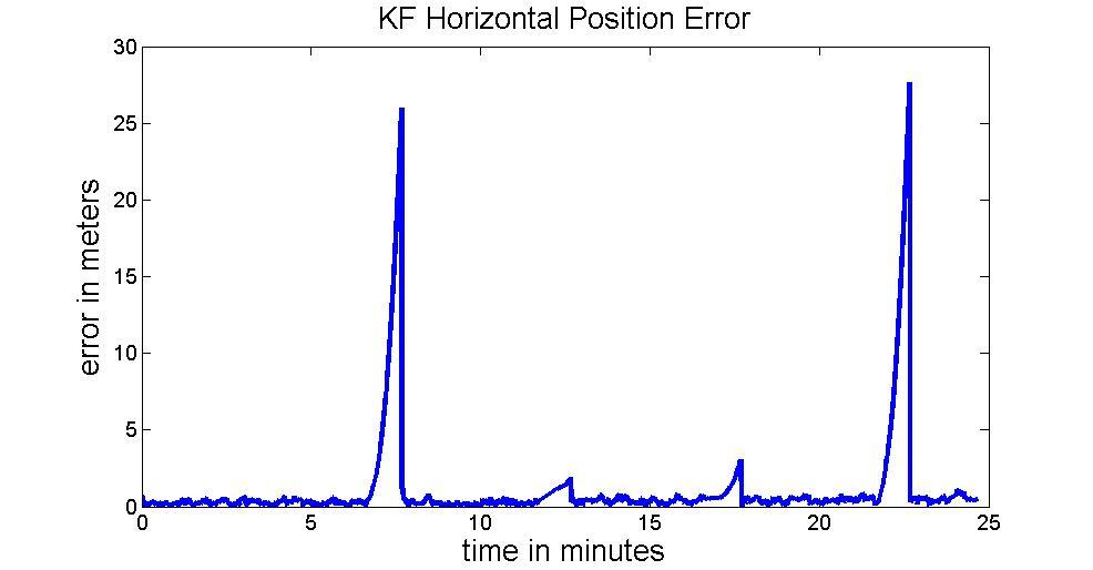
This simulator provides an easy way to understanding the behavior while tuning the matrix. Figures 15 and 16 illustrate the results with well-tuned and improper Q matrices, respectively.
Figure 15: Well-tuning KF
It clearly sees that when GNSS outage occurs the INS performance with impropriety Q will cause position error growing faster than a fitter one. There are four GNSS outage assign to the simulation. Each of them lasts 60 seconds. The maximum position error in GNSS outage can reach about 26m and its RMS is 11.4987m as shown in Figure 16. Comparing to well-tuning Q, the maximum of position error is only about 2.6m and its RMS is 1.508m.
The need to re-design algorithms based on the Kalman filter (i.e., states) to operate adequately and efficiently on every new platform (application) or different systems (i.e., switch from navigation grade IMU to tactical grade IMUs) can be very costly. In addition, the Q and R matrices tuning is heavily system dependent. For example, it is impossible to use the sets of parameters that are designated for navigation grade IMU for the estimation utilizing tactical grade IMUs. By using the proposed simulation platform, user can appreciate the filter tuning process using various “pseudo” IMUs with different accuracies. In this case, it can be used as a tool to train people how to tune the Q matrix theoretically according to the grade of IMU selected without actually getting a pricy IMU and conducting time consuming filed tests.
Figure 16: Improper Q matrix
The comparison between loosely coupled EKF and RTS
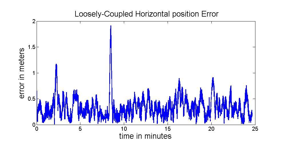
Figure 17 illustrates the results of the commonest INS/GNSS integrated architecture. The RMS of positional errors is 0.4013m. No GNSS outage is simulated in this case.
Figure 17: Result of Loosely-coupled with good GNSS
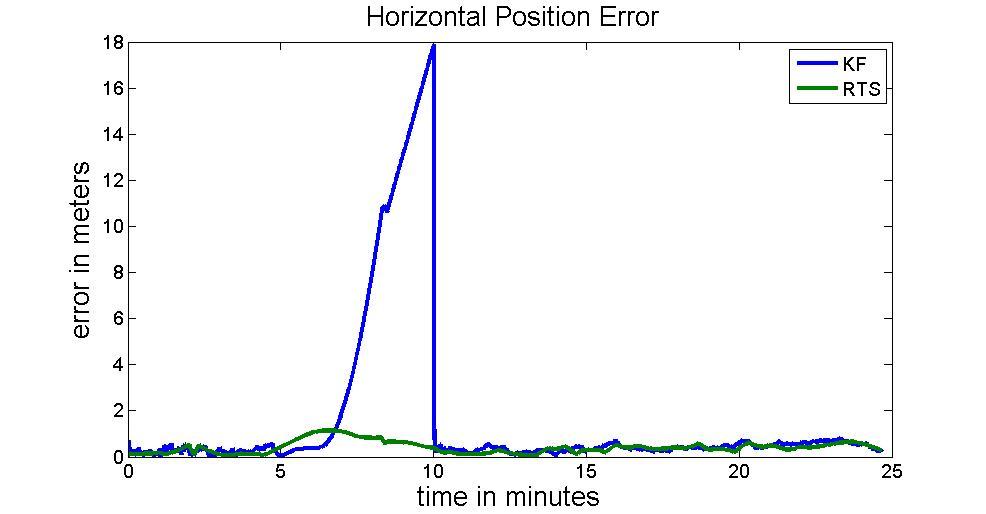
Figure 18 compares the results of EKF and RTS smoother with a segment of simulated GNSS outage with 5 minutes in length. .The RMS of positional error arises to 8.78m. On the contrary, The RTS smoother did a great job compensating the state vector during GNSS outage. Therefore, the position RMS after using RTS smoother can be reduced to 0.83m. The improvement in term of positional error after applying RTS smoother reaches 90%.
Figure 18: 300s GNSS outage
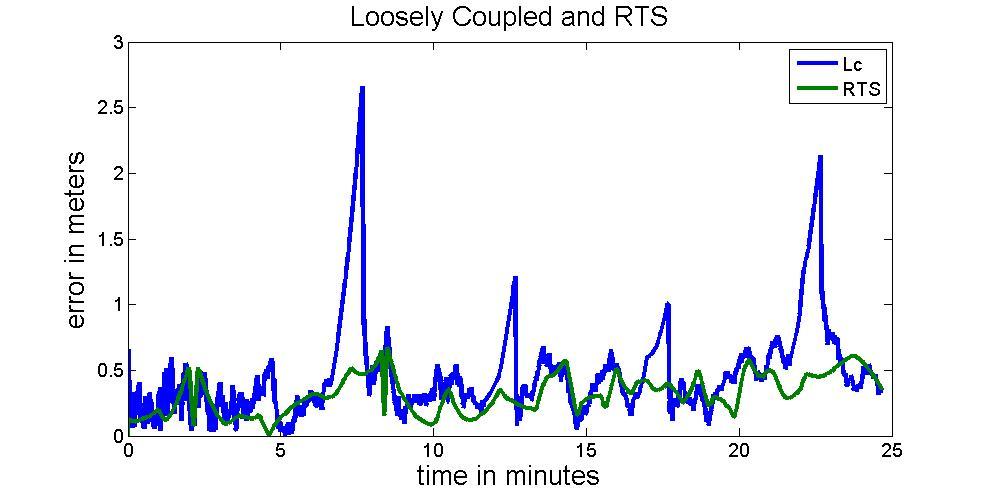
Figure 19 illustrates the performance of EKF and RTS smoother during frequent GNSS outages. Table 2 illustrates the RMS values of positional errors during simulated GNSS outages for EKF and RTS smoother, respectively.
Figure 19: Four 60s GNSS outage
Table 2 RMS in GNSS outage (Loosely-Coupled only)

The comparison between tightly coupled EKF and RTS
The number of satellite in view is an interesting problem when the tightly coupled integration architecture is implemented. Figure 20 illustrates the performance of the tightly coupled architecture when no GNSS outages occur. The RMS of positional error is 0.4754m, which is similar to the result of the loosely couple architecture, as shown in Figure 17.
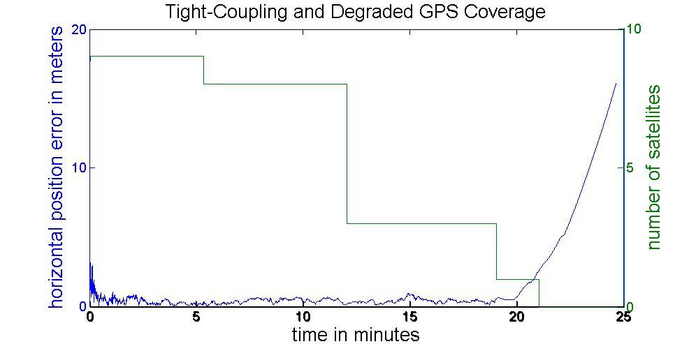
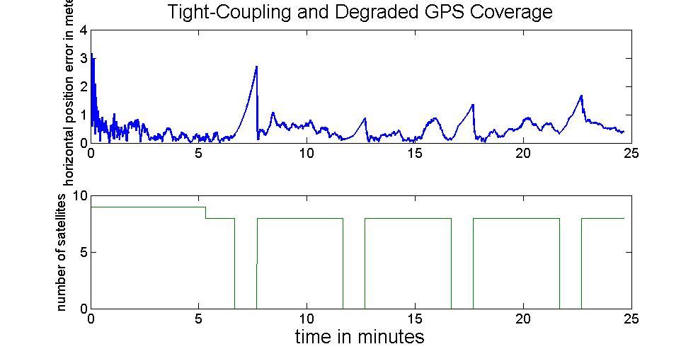
When degraded GNSS coverage occurs, the advantage of tightly-coupled appears. Figure 21 illustrates the situation of degrading GNSS coverage. When the number of satellites becomes less than 4, the tightly coupled architecture can still provide reasonable position solution. Figure 22 illustrates the performance of tightly coupled architecture during frequent GNSS outages. The above figure indicates the performance when there is no GNSS signal available and lower one illustrates the variation of the satellite in view. Table 3 illustrates the RMS values of the positional error during each GNSS outage. With no satellite in view during those GNSS outages, the performances of loosely coupled and tightly coupled architectures are quite the similar, see Tables 2 and 3 for comparison.
Figure 20: Tightly-Coupled with well-condition GNSS
Figure 21: Tightly-Coupled with GNSS Degradation
Figure 22: Tightly-Coupled in GNSS outage
Table 3 RMS in GNSS outage (Tightly-Coupled only)

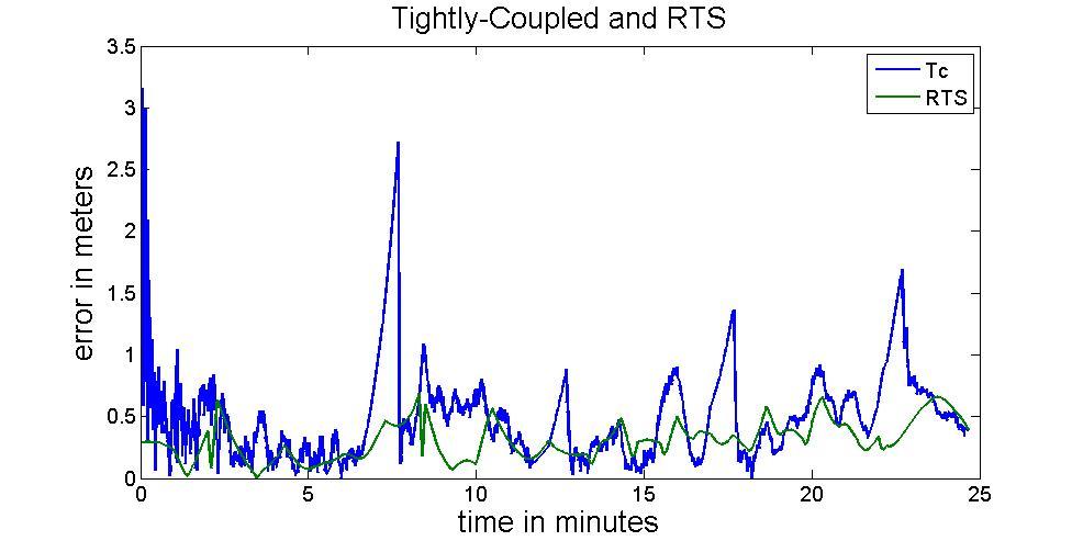
Figure 23 compares the performance using EKF and RTS smoother, respectively. The RMS values of positional error after applying RTS smoother is given in Table 3.
Figure 23: Tightly-Coupled and RTS
The comparison between loosely coupled and tightly coupled EKF
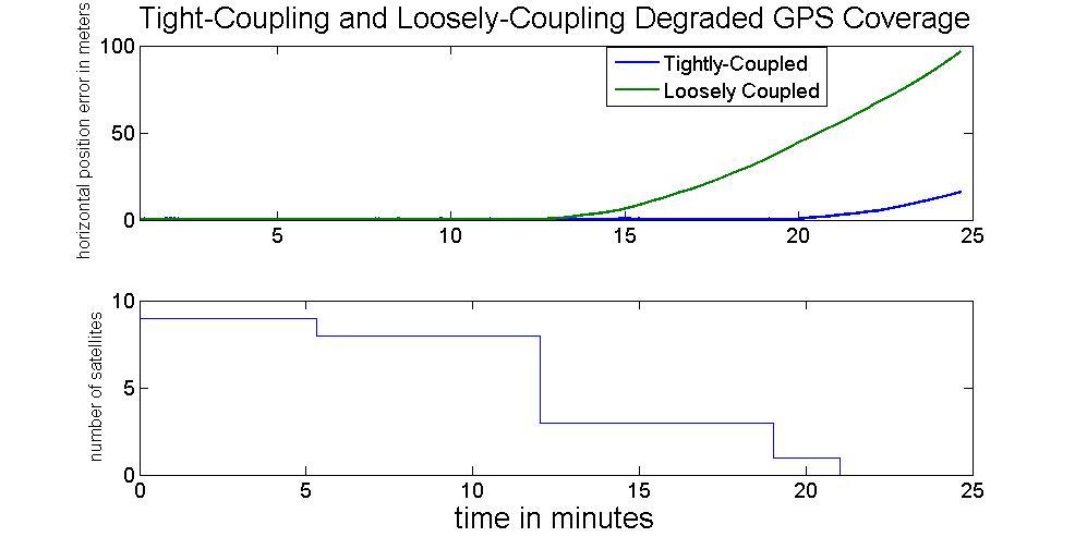
After discussing the performance of loosely coupled/tightly coupled EKF and RTS smoothers, Figure 24 illustrates the performance between the loosely coupled and tightly coupled EKF when degraded GNSS coverage occurs. While received GNSS signal become less than 4 satellites, the loosely coupled EKF can’t provide integrated navigation solution but the tightly coupled EKF still work properly till there is no satellite available.
Figure 24: Loosely-Coupled and Tightly-Coupled in GNSS degradation
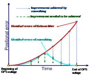
Figure 25 illustrates a conceptual plot concerning the impact of the RTS smoother on the positioning error in case of a GPS outage. As illustrated in Figure 25, the use of RTS smoother is able to remove the residual errors of KF significantly; however, some residual errors still remain. It can be seen that the proposed INS/GNSS simulation platform can not only emulate measurements for advanced algorithms research but provide optimal estimation engine for investigating some practical issues concerning the development of INS/GNSS integration algorithm. Therefore, it is a cost effective tool not only for research but for education as well. It becomes easier in studying INS/GNSS integration algorithm and Kalman Filter arguments tuning through the simulator. Without experience hardware, it totally composes of software thus the system becomes more fixable.
Figure 25: The impact of RTS smoother on positional error during outage
Conclusions
This study exploits a complete INS/GNSS simulation platform. Its architecture includes trajectory generator which can generate all kind of trajectory by user defined. Measurement generator created IMU and GNSS measurements according to the user designed path data and senor error model. Estimator has two different data process strategy, feedforward which suit for high grade IMU and feedback for tactical grade or MEMS IMU. Besides, The EKF and RTS smoother are implemented by loosely coupled and tightly coupled integration architecture.
It will become easier in studying INS/GNSS integration algorithm and Kalman Filter arguments tuning through the simulator. Without expensive hardware, it totally composes of software thus the system becomes more fixable. Not only in study but also the result of simulation also can be the principle of IMU purchase. User can easy create a varied environment where desired IMU is expected to work. Then through simulation, the adaptive IMU can be selected. In the future, not only in the high demand of accuracy in mapping or low-cost navigation for personal use, this simulator can provide precise simulation as possible. To reach all kind of demands, the estimation process engine is implemented to process real measurement as well.
Acknowledgments
The authors would like to acknowledge the financial support by the National Science Council of the Executive Yuan, ROC (Taiwan) (NSC 95-2221-E-006 -335 -MY2).
References
1. Bennour, Z., Landry, R. Jr., Giroux, R. Constantinescu, A., and Gavidia, G. (2005). Web-Based MEMS Inertial Navigation Simulator, ION 61st Annual Meeting 2005, Cambridge, MA
2. Brown R.G. and Hwang P.Y.C. (1992): Introduction to random signals, John Wiley and Sons, New York, 1992.
3. Chiang, K.W.(2004). INS/GPS Integration Using Neural Networks for Land Vehicular Navigation Applications, Department of Geomatics Engineering, The University of Calgary, Calgary, Canada, UCGE Report 20209.
4. El-Sheimy, N. (2004) Inertial Techniques and INS/DGPS Integration, ENGO 623 lecture notes, Department of Geomatics Engineering, The University of Calgary.
5. Gelb A (1974) Applied Optimal Estimation. MIT Press, Cambridge, England.
6. Schwarz, K.P. and M. Wei.(2001). INS/GPS integration for Geomatics. Lecture Notes for ENGO623, Department of Geomatics Engineering, the University of Calgary, Calgary, Alberta, Canada.
7. Titterton, D. H. and Weston, J. L. (1997): Strapdown Inertial Navigation Technology, Peter Peregrinus Ltd.
8. Yang, Y., El-Sheimy, N., Goodall, C., and Niu, X. (2007) IMU Signal Software Simulator, ION NTM 2007, San Diego, CA
My Coordinates |
EDITORIAL |
|
His Coordinates |
Paul Verhoef |
|
Mark your calendar |
NOVEMBER 2010 TO AUGUST 2011 |
|
News |
INDUSTRY | LBS | GPS | GIS | REMOTE SENSING | GALILEO UPDATE |





 (No Ratings Yet)


Leave your response!