| Positioning | |
Status of the GNSS Transmitter-Based Approach for Indoor Positioning
A very interesting feature of the transmitter approach is the possibility to locate transmitters underneath the receiver |
|
 |
|
||||
 |
|
||||
 |
|
||||
 |
|
||||
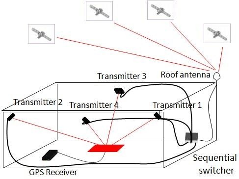
The transmitter-based approach is an indoor positioning method, based on the use of a local infrastructure, aiming to provide accuracies of 1 to 2 meters. The GNSS signals are received by an outdoor antenna located in a place with an unobstructed view of the satellites. Note that another possibility is to use a GNSS signal generator (generating one or 4 satellites) instead of the outdoor antenna. Furthermore, these signals are amplified and transmitted to a set of four antennas located indoors, the so-called “transmitters”, which transmit the signals indoors (see Fig. 1).
Fig.1: Principle of the GNSS transmitter-based approach
The four transmitters all broadcast the same signal, but in a sequential way, thus creating a transmission cycle. At the exact instant of the transition from one transmitter to the next, a variation of the distance between the transmitter and the indoor receiver occurs. This variation induces an offset in the phase of the received signal. The principle is to convert this offset (also called phase jump) into a distance in order to obtain the difference of distances between the successive transmitters and the indoor receiver. After a complete cycle, one has four such differences available and may carry out the indoor 3D location computations.
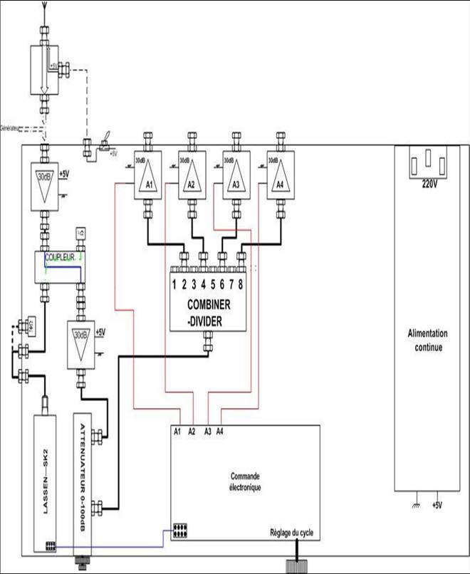
In the current version, an electronic box (see Fig. 2) carries out the amplification, the cycling and the splitting of the signals towards the four transmitters. Please note that the cycling is synchronised to the GPS time through the use of a GPS receiver, included in the electronic box.
Fig.2: Principle of the electronic box
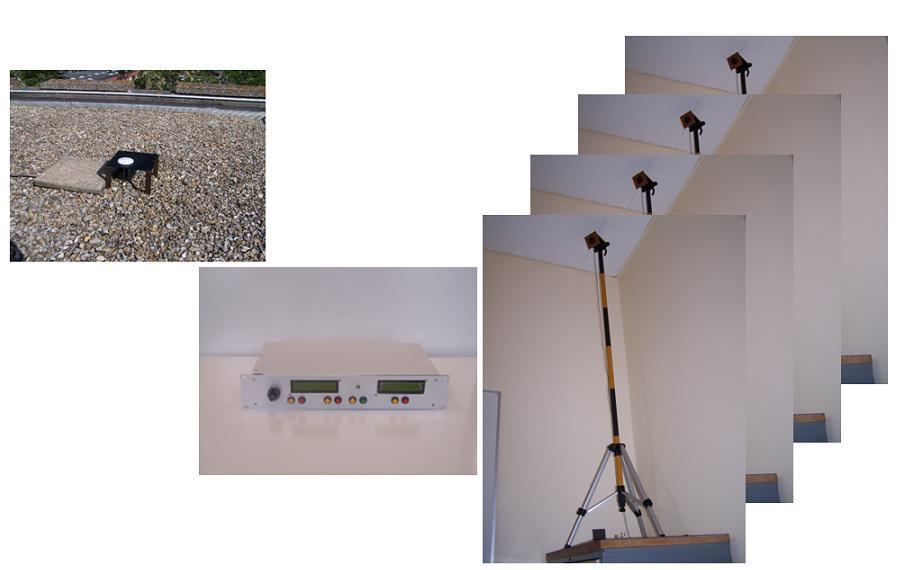
The complete transmitter system (shown in Fig.3), composed of the outdoor GPS receiving antenna (or the GNSS signal generator), 4 indoor transmitter antennas, transmission cables and the electronic box, is low-cost and easy to transport and deploy. Current work is focused on replacing the coaxial transmission cables with other techniques (mainly optical fibre), making the deployment of the system even easier.
Fig.3: Current implementation of the transmitter system
A very interesting feature of the transmitter approach is the possibility to locate transmitters underneath the receiver. This distribution allows a very good vertical Dilution Of Precision to be provided, as good as the horizontal one. Another important aspect is the “time differential” approach implemented with the transmitters, which allows for an improved theoretical accuracy.
Regulatory framework for GNSS repeaters and pseudolites
Regulations tend to be provided for repeaters and pseudolites. The ECC Report 145 (Electronic Communications Committee) presents some conclusions concerning the use of repeaters [1]. It is recommended that GNSS repeaters be individually licensed, and the technical and operating conditions that should be taken into account for the licensing are specified. ETSI (European Technical System Institute) has also adopted a harmonised standard for GNSS repeaters [2]. In the frequency band under consideration (1559 – 1610 MHz), the protection to non-participating GNSS users has to be ensured by some gain/power limitations.
It should be noticed that there is a fundamental difference between the repeaters mentioned in the ECC Report 145 and the transmitters used in our approach. Indeed, the repeaters are simply receiving the GNSS signals and re-radiating them inside building, in order to provide a usable signal. Thus, they can cause harmful interference to the other GNSS users. The transmitters used in our approach can use any type of signal (e.g. the codes of the non-visible satellites or the PRN codes 33 to 36, reserved to the pseudolites), so interference is dramatically reduced.
Taking into account these considerations, it is more appropriate to apply the pseudolites regulations to our transmitter-based system.
For the moment there are no finalized regulations concerning the pseudolite use, but the restrictions being discussed seem to be less limiting than for the repeaters. Anyway, the only impact on the transmitter-based approach is in relation to the number of transmitters to be deployed in order to ensure full coverage of the environment considered. Simulations performed to this end [3] showed that it is possible to cover in 3D a 4 floors building of 35 x 16 x 13 meters with only four transmitters, if the transmitted power is -63 dBm. If we consider an emission power of -77 dBm (corresponding to the repeater regulations indicated in ECC Report 145), eight transmitters are needed to cover the same building.
Developments and validations
For many years the Navigation Group at Telecom SudParis (TSP) has been working on the transmitter-based approach. Various research and development projects have been oriented in three main directions:
– Multipath propagation simulations and electromagnetic modelling of indoor environments
– Developments of new receiver architectures
– Real implementations of the configurations obtained, and experiments
These themes, briefly discussed in this paragraph, allowed us to develop the transmitter-based approach until the final form it has today and to show the real potential of this method.
Multipath propagation simulations
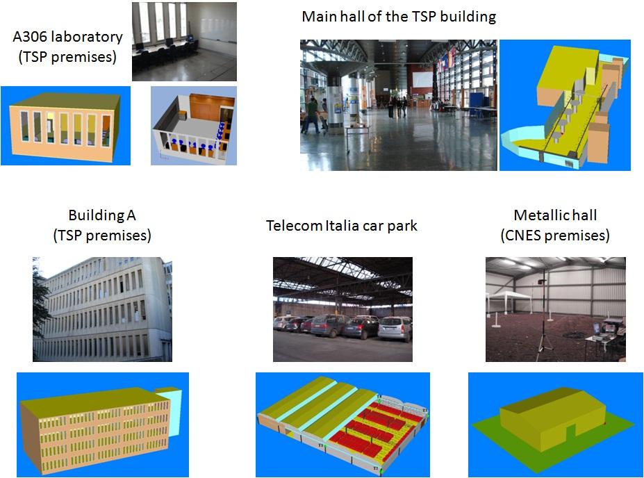
In order to provide us with a better understanding of the multipath effects and some deployment rules for the transmitters, multipath propagation simulations were performed using Ergospace, a deterministic propagation simulation software. Various indoor environments have been modelled using VRML (Virtual Reality Modelling Language), and are presented in Fig.4:
• the A306 laboratory (6.5m x 6.8m x 3.3m), located on the third floor of TSP
• the main hall of TSP, a large space of 70 meters by 15 meters, with a ceiling height ranging from 4 to 7 meters
• the building A of TSP (4 floors including staircases and elevators, 34.3m x 16m x 13.3m)
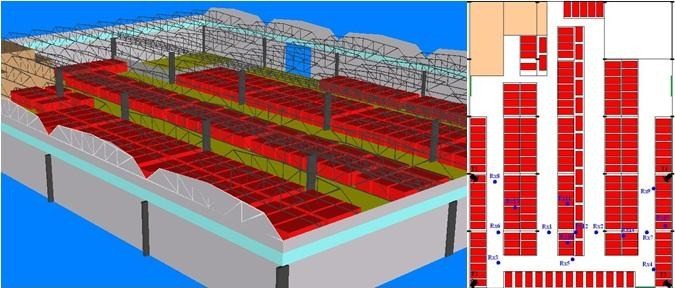
• the car-park of Telecom Italia in Turin (34m x 60m) with a height ranging between 7 and 9 meters
• an almost empty metallic hall in the CNES premises, Toulouse (28.8m x 24.5m) with a ceiling height from 4.5 to 5.8 meters
Fig.4: Various indoor environments studied and their VRML models
The Ergospace simulations performed in these environments had various goals:
• Determination of all multipath characteristics at a given receiving position (power, delay, phase, Doppler shift).
Simulations were performed in the A306 laboratory [4] and the main hall of TSP [5] in order to provide us with a better understanding of multipath propagation. Also, the a priori knowledge of multipath characteristics helped us to prepare measurement campaigns.
• Construction of power maps in buildings.
Power maps were simulated in the building A of TSP in order to evaluate the coverage distance of the transmitters as a function of the emission power and the threshold level of the receiver considered [3].
• Determination of the number of transmitters in visibility.
In order to define the number of transmitters necessary to satisfy the on-going regulations and to provide us with optimal deployment rules for the transmitter antennas, simulations were performed in the building A [3]. To this goal, the number of transmitters in visibility was determined by simulation in each point of the environment.
• Study the influence of the transmitter antenna pattern.
Two types of antennas were studied in [5], the Macon passive patch antennas, characterized by a maximum gain of approximately 3 dB and a half-power beamwidth of 120°, and the Tecom helical antennas, with a maximum gain of 13.2 dB and a higher directivity (32° half-power beamwidth).
• Study the effect of limited displacements around a given location, in order to evaluate the small scale variations of the multipath.
Simulations have been performed in the main hall of TSP for various positions of the transmitters and of the receiving antenna in an area of approximately one λ around a considered location [6].
Developments of new receiver architectures
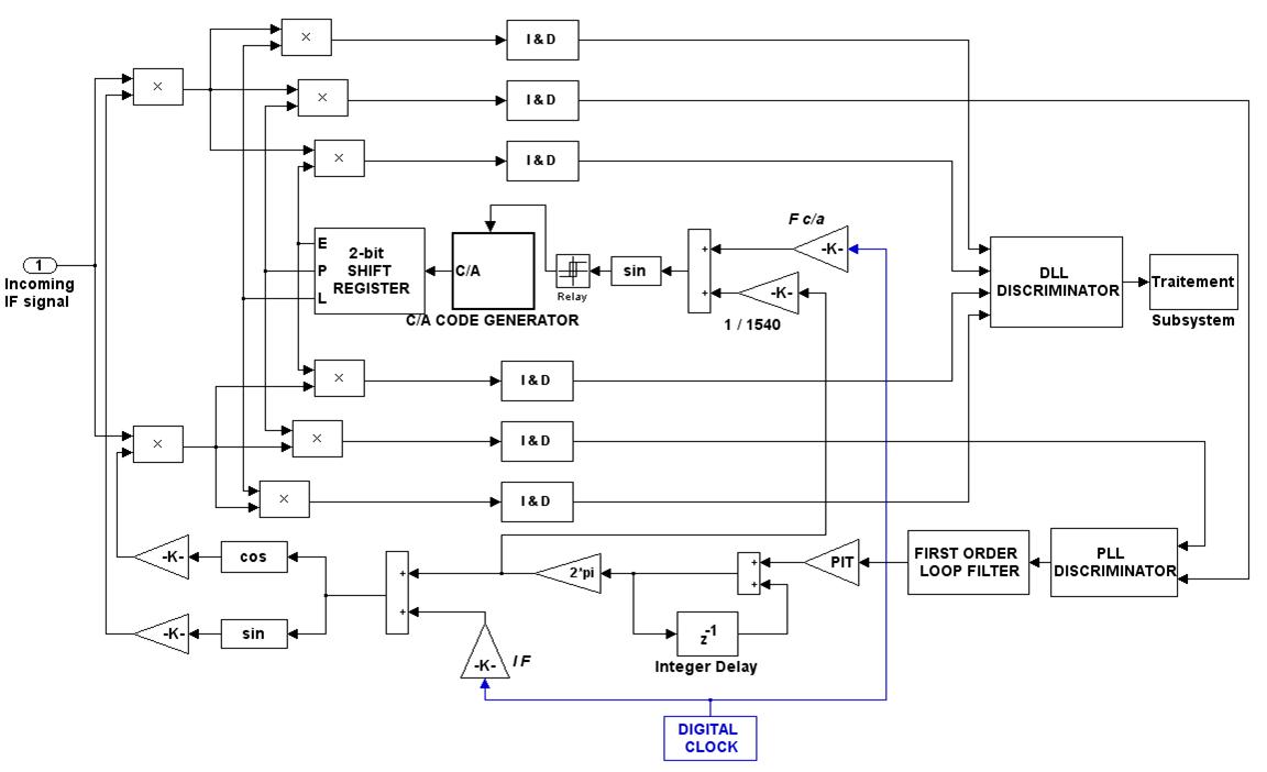
In order to improve the phase jump measurements, especially against thermal noise and multipath, we developed new code loop architectures adapted to the transmitter-based positioning system, but not restricted to it: the “open” loop and the “SMICL” loop.
The open tracking loop discriminator
The open tracking loop discriminator, developed in order to reduce the thermal noise is presented in Fig.5. The principle is very simple: the carrier loop is preserved while the code loop is open [7].
Fig.5: Implementation of the open code loop
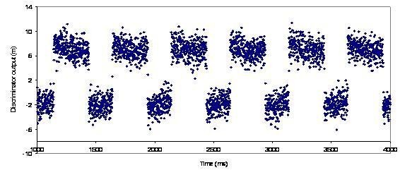
Thermal noise is modelled by a zero mean Gaussian process. Thereafter, an effective way to minimize the effect of the noise is to average the output of the code loop discriminator over each transmission time when the code loop is open (see results in Fig. 6).
Fig.6: Open loop – discriminator output (top: simulation results bottom: real implementation results)
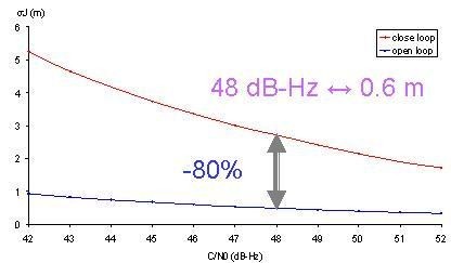
The phase jump is obtained by computing the difference between two successive averages. Fig.7 shows the standard deviation error of the phase jump measurement for the standard and the open loops.
Fig.7: Open loop – Phase jump error as a function of C/N0
One can observe that the noise effect is dramatically reduced by the open loop (with a noise reduction factor greater than 5). For a carrier to noise ratio of 48 dB-Hz, the error is 0.6 m. The proposed open loop was implemented on a NordNav R30 software receiver, leading to full agreement with the theory.
The SMICL tracking loop discriminator
The SMICL loop [8] – Short Multipath Insensitive Code Loop – was developed in order to mitigate the short multipath (with delays of less than 0.5 code chip), which are the problematic ones indoors. This discriminator traditionally uses the three complex correlators. It is conceived such that it outputs zero when the prompt replica code becomes synchronized to the direct signal, whatever the multipath. The circuit of the new code loop is presented in Fig.8. It has the advantage of being simple and does not require any specific hardware or post-processing of observables.
Fig.8: Implementation of the SMICL code loop
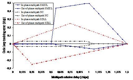
Tracking error envelopes assuming a noise-free environment are given in Fig.9 for the SMICL loop, the standard DLL (SDLL) and the narrow correlator (NC). Based on these results, SMICL shows a dramatic improvement over the other techniques for multipath having relative delays less than 146.5 meters.
Fig.9: Maximum multipath noise-free tracking error comparison.
Ergospace simulations performed in the main hall of TSP [9] confirmed the advantages of the SMICL loop:
Real implementations and deployments
Various measurements campaigns were performed. We present here only the results obtained during the last measurement campaign, performed in the car-park of Telecom Italia, in Turin, using an IFEN NavX 10 MHz receiver [10]. The signal was generated by a Spirent GSS6560. The results presented below are based on raw positioning data obtained in the 15 receiving positions studied in the environment (Rx1 to Rx15 in Fig.10).
Fig.10: Measurement campaign in Telecom Italia car park, Turin
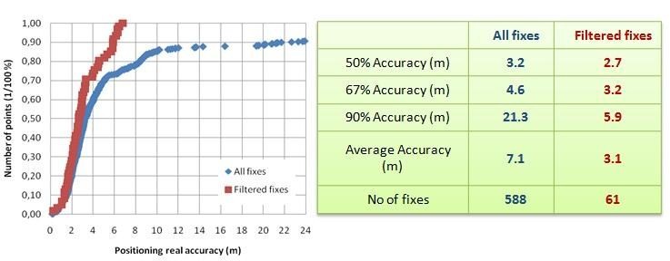
It has been found that an implementation of the SMICL loop with a shift of 0.008 chips of the horizontal axis (in order to help the loop find the zero crossing point) gives the best results. Fig.11 shows the real positioning accuracy achieved for all the fixes, with no processing of the data, except for removing the fixes located outside the polygon defined by the locations of the transmitter antennas (increased by 1 meter in order to consider a slight error margin). Outside this polygon, the DOP values increase very rapidly and classical positioning computation is of very poor quality.
Fig.11: Real accuracy for all the fixes
Some processing approaches were proposed in order to improve the accuracy of the results: it has been found that the results are greatly improved by filtering the fixes with an accuracy standard deviation greater than 3 meters (compared to the mean accuracy obtained by averaging all the accuracies of each individual fix) as well as the ones with fewer than 4 satellites capable of computing a fix. Taking into account these techniques, the accuracy decreases to 2 to 3 meters, results in good agreement with the theoretical expectations for a 10 MHz receiver. Increasing the bandwidth is bound to further decrease the accuracy value, down to 1 to 2 meters (theoretical result). Fig. 12 shows the comparison of real accuracies obtained for the “non-filtered” and “filtered” approaches.
Fig.12: Comparison of real accuracies obtained for the “non-filtered” and “filtered” approaches
Conclusions & future work
This paper has presented the latest updates of the GNSS transmitter-based approach, highlighting its advantages in terms of performances, cost and simplicity of the infrastructure. It should be noticed that this system, easy to deploy and transport, can be used for instance in a non-equipped building or even outdoors. Such a deployment could be envisaged in a situation of emergency, for fire brigades or police operations, in a building where no indoor positioning equipment is available.
Various research and development projects, validated by measurements or simulations, lead us to a finalized system, proving interesting features and performances for indoor localization. Furthermore, we have reached the step where having a finalised proof-of-concept of the transmitter based approach and implementing the SMICL tracking loop on a suitable receiver requires the technical skills of a GNSS manufacturer.
We are focusing now on a new approach based on the use of “repealites”, which is intended to provide sub-metric indoor positioning [11]. The repealites represent a compromise between GNSS repeaters and pseudolites, taking advantage of both techniques in order to allow carrier phase measurements and yet avoid the synchronisation limitations of pseudolites. The first results are very promising and experimental validation is already planned.
Acknowledgements
We want to thank CNES and Telecom Italia for partial funding. An additional thank you to Jenoptec, the French distributor of Spirent, for the loan of a GSS6560.
References
[1] http://www.erodocdb.dk/Docs/doc98/Official/word/ – ECCRep145
[2]http://www.etsi.org/deliver/etsi_en/302600_302699/302645/01.01.01_60/en_302645v010101p.pdf
[3] A. Fluerasu and N. Samama, GNSS transmitter based indoor positioning systems – Deployment rules in real buildings, IAIN2009, Stockholm, Sweden, October 2009.
[4] A. Fluerasu, N. Jardak, A. Vervisch-Picois, M. Jeannot, M. Boschetti, N. Samama, “Study of Multipath Effects for the GNSS Repeater Based Indoor Positioning Technique”, ION GNSS 2007, Forth Worth, USA, September 2007.
[5] A. Fluerasu, N. Jardak, M. Boschetti, N. Samama, “ Multipath Modelisation of Typical Indoor Environments -Optimisation of GNSS Based Indoor Positioning”, ENC-GNSS2008, Toulouse, France, April 2008.
[6] A. Fluerasu, N. Jardak, A. Vervisch-Picois, N. Samama, “GNSS Repeater Based Approach for Indoor Positioning: Current Status”, ENC-GNSS2009, Naples, Italy, May 2009.
[7] N. Jardak, A. Vervisch-Picois, M. Jeannot, A. Fluerasu, N. Samama, “Implementation of an Optimized Code Loop for Indoor Positioning”, ION GNSS 2007, Forth Worth, Texas, USA, September 2007.
[8] N. Jardak, A. Fluerasu, A. Vervisch-Picois, M. Jeannot, N. Samama, “ Optimized Tracking Loop for Multipath Mitigation Case of Repeater Based Indoor Positioning System”, ENC-GNSS2008, Toulouse, France, April 2008.
[9] A. Fluerasu, N. Jardak, A. Vervisch-Picois, M. Boschetti, N. Samama, “Multipath effects on the GNSS repeater based approach. Tracking loop discriminator impact on multipath mitigation”, ENC-GNSS2009, Naples, Italy, May 2009.
[10] A. Fluerasu, A. Vervisch-Picois, G. Boiero, G. Ghinamo, P. Lovisolo, N. Samama, “Indoor Positioning Using GPS transmitters: Experimental results”, IPIN 2010, Zurich, Switzerland, Sept. 2010.
[11] A. Vervisch-Picois, N. Samama, “Indoor Carrier Phase Measurements Through GNSS Transmitters Theory and First Experimental Results”, IAIN2009, Stockholm, Sweden, October 2009.
http://www.asc.rssi.ru/radioastron/index.htm
My Coordinates |
EDITORIAL |
|
Mark your calendar |
FEBRUARY 2011 TO NOVEMBER 2011 |
|
News |
INDUSTRY | LBS | GPS | GIS | REMOTE SENSING | GALILEO UPDATE |







 (2 votes, average: 1.00 out of 5)


Leave your response!