| Mycoordinates | |
GPS based control points for mapping
|
||||
|
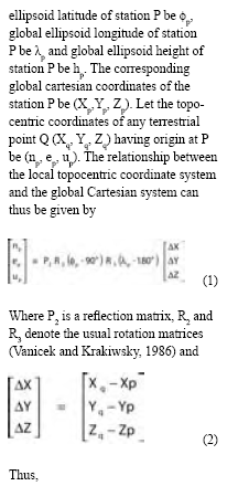
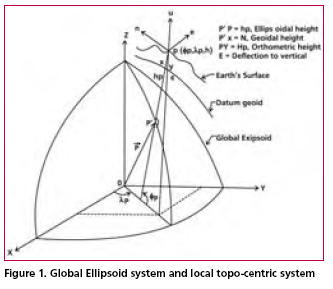
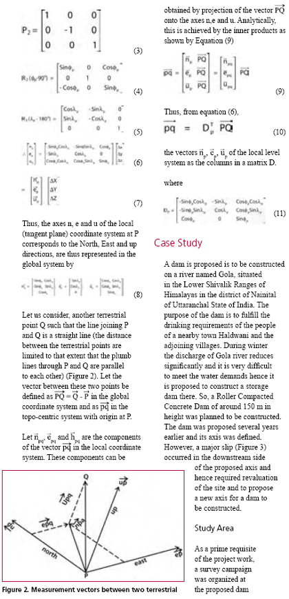
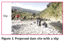
To carry out the infrastructural development in any area, topographical maps (accurate, reliable and updated) of that area are of vital important. Topographic maps are also important aids for administrative and strategic planning, disaster mitigation, socioeconomic development and other related activities. In order to prepare topographic map, it is prerequisite to have grid coordinates as well as elevations of control points. GPS has already been used as an important tool for establishment of control points accurately, quickly and economically in a versatile way. Though it provides precise planimetric position of a station but it provides gross imprecision in height (Ghosh and Rao, 2001). Moreover, the coordinates of the points are obtained in the WGS 84 reference system, a global coordinate system. But, for preparation of topographic maps, cartographers are in need of grid coordinates in local (topocentric) coordinate system. To find the local coordinates from global coordinates, transformation parameters between the local and the global system are required which requires at least known three common stations. But, due to security reason, often the precise local geodetic coordinates of control points are not made available to civil users. The problem of non-availability of local geodetic coordinates can be circumvent by adopting an appropriate method. The objective of this paper is to discuss a simple method for finding out the grid coordinates as well as elevation of control points in a topocentric coordinate system using GPS data followed by a case study implementing the method. MethodologyTo prepare a topographic map, it is a usually convenient to have grid coordinates in a topocentric coordinate system having geographic North, East and Vertical up directions as the three reference axes. In this section, Let the spatial orientation of the local coordinate system with origin at P is specified by the global geodetic coordinates site on River Gola. It was proposed to carry out a topographic surveying and mapping of an area of about 800 meter long and 300 to 400 meter wide in the bed of Gola river. Since the duration of surveying work was limited, it was planned that area to be surveyed is divided into parcel of land across the river having over lapping in each side. It was decided that each area would be provided with control points. To obtain accurate, quickly as well as easily, control points were planned to be established through GPS. Thus, coordinates of the terrestrial points are thus obtained are in a global system. But to prepare of topographic maps, topocentric coordinates of the control points are required. The requirement was met by transformation of global coordinates into topocentric local coordinates as discussed in previous section. |
||||
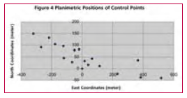
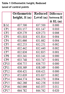
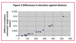
Observation and ResultThe observation was taken on December 29, 2002 starting from 09hr 31min 55sec to 16hr 46min 55sec i.e., a duration of 7 hr 15 min starting from morning to evening. On next day i.e, on December 30, 2002 the observation session started at morning (08 hr 31 min 30 sec) and continued till evening (14 hr 32min 25 sec) for a duration of 6 hr 12 min 55 sec. The observed data was processed in SKI 2.3 in relative positioning mode. Dual frequency data were used in processing. Broadcast ephemerides were used to compute the position of satellite. Hopfield model was used to take into consideration the delay caused by troposphere but no model was used for ionospheric interference. After processing the data, positions of the B.M. and other control points have been found in WGS 84 coordinate system. The global coordinates thus found are then converted to local Cartesian Coordinates (Topocentric System) with origin at B.M. using the Equation (10). The local Cartesian Coordinates of the control points are obtained considering B.M. as origin. A plot of the planimetric position of the control points is as shown in Figure 4. To find the vertical position of the control points two types of heights i.e., orthometric height and reduced level have been found. The concept of datum transformation (Hofmann- Wellenhoff, 2001) has been used to find orthometric height. In this, first the amount of geodetic undulation at the B.M. is calculated from geodetic height (606.794 meter, found from GPS obsevation) and the orthometric height (637.5000 meter) as established field data. This has been found to be 30.706 meter (637.500- 606.794). The reduced level (R.L.) of the control points are calculated using the R.L. of the B.M (637.5000 meter) and the difference in vertical elevation (z) between the B.M. and that of considered control point [as found by the transformation equation (10) given in Table 1, the z component]. The orthometric height and the R.L. of all the control points thus obtained are as shown in Table 1. DiscussionTo minimize the inherent errors associated with in GPS observations (Leick, 1995) due precausion had been taken all throughout the campaign. Moreover, observations were taken in relative positioning mode and the area surveyed is small thus it has been assumed that the residual error, if any, is the same for all points. The topo-centric local grid coordinates of control points are calculated from GPS observation. A transformation matrix based on geodetic coordinates of the origin (based on GPS observation in the global geodetic system) has been used and no other data is required for finding out the planimetric positions. The vertical height of points are also found from the same GPS observation. Thus, all the three components of the position of any control point are based on same set of GPS observation. This helps in minimizing the field work drastically over the traditional methods. The elevation of points has been found by adopting two independent methods using the same set of GPS observation. First one is the method of datum transformation. In this method, the orthometric heights of points have been found. Since, the distance between origin and other points are small with respect to geodetic consideration, it has been assumed that the difference in the angle of deflection to vertical (e) between the origin and other points is negligibly small. Next, the reduced level (vertical elevation) of control points are calculated using the vertical height (found by transformation matrix) and R.L. of B.M. These heights are found to be mostly equal to that of orthometric heights. The deviations of R.L. from orthometric heights within the study area noted to be increasing with the distance from origin (Figure 5) but do not depend on the height of points above origin (figure 6). Thus, the variation in heights may be attributed to the variation in geodetic undulation with distance, as expected since the terrain is hilly. Further, the grid coordinates thus calculated can easily be related to other local or global network as the considered directions (north, East and vertical) of axes are universal and origin (B.M.) is well established. ConclusionTransformation of GPS observation will help cartographers by providing a topo-centric coordinate system with B.M. as origin. This method results in very accurate positioning of control points for a small area. This method is quite simple and easier than conventional transformation methods. Moreover, this will lead to overcome the problem of non-availability of precise geodetic coordinates of control points. Determination of vertical height of points is quite simple. However, to restrict the amount of accuracy within desired limit, the variation of geodetic undulation at the site is to found before further surveying operation. The areal extent to which the undulation deviates from that of the origin within the permissible limit (depending on the desire accuracy of the campaign) first better be determined. Thus, if area to be surveyed is large and the desired accuracy is high, a number of bench marks are required to be available in the site or to be established first and subsequently, the command area for mapping using GPS observation around the bench marks are to be found. AcknowledgementStudents of B.Tech (2002-2003) Final year (Civil) of IIT Roorkee for collecting the data. Authors also acknowledge the help rendered by Prof A.K.Mathur and Dr. M.Singh in organizing the survey campaign successfully. ReferencesGhosh, J.K. and Ch. V.A. Rao, (2001). GPS Control Point Positioning. Asian GPS Conference held at New Delhi (October 29-30, 2001) pp 43-46. GPS Positioning Guide – Geomatics Canada, Geodetic Survey Division Ottawa, Canada. Hofmann-Wellenhof, B, H.Lichtenegger and J.Collins, 2001. GPS Theory and practice (5 th Ed), Springer Wien, NY, pp 382. Leica GPS- System 300 “Guidelines to Static and Rapid Static GPS Surveying”, May 1995. Leick, A (1995). GPS Satellite Surveying (2nd Ed), John Wiley & Sons, NY pp 560. Vanicek, p and E.J. Krakiwsky, 1986. Geodesy: the Concepts, Elsevier Science Publishing Company Ltd pp 697. |
|||||||||||||||||||||||||||||
|
|||||||||||||||||||||||||||||
|
Pages: 1 2



 (No Ratings Yet)


