| Navigation | |
A Study on GPS/DR Car Navigation System using Vehicle Movement Information
The integrated GPS/DR navigation system provides an appropriate performance under GPS blockage condition. |
|
 |
|
||||
 |
|
||||
This paper describes the performance improvement of GPS/DR (Global Positioning System/Dead Reckoning) Integration system utilizing the area decision algorithm and vehicle movement information. In GPS/DR Integration system, generally DR sensor errors are estimated and corrected using GPS information when GPS is available. In GPS signal blockage area, i.e., tunnel and underground parking area, DR sensor errors are accumulated and navigation solution is diverged eventually. We utilize the car movement information and area decision algorithm to reduce accumulated DR sensor error. The vehicle movement information is obtained by analyzing the DR sensor data. The car movement is divided into stop, straight line, turn and movement changing region. The car experiment is performed to verify the proposed method. The results show that proposed method provides smaller position and heading error than previous method. When GPS is blocked in 300 sec, the position error is smaller than 9 times in straight line area and 3 times in turn area.
Introduction
Recently the car navigation systems have been widely installed in many vehicles. Generally the car navigation system uses navigation information obtained from GPS (Global Positioning System) satellite signal because GPS provides good navigation information to user when GPS signal is available. However GPS does not work well in an underground parking area, tunnel and urban areas due to signal blockage or attenuation. The GPS and DR (Dead Reckoning) sensor integration can be one of the solutions. GPS shows a long-term error performance, on the other hand, DR sensor shows a good performance in short-term. So the integrated GPS-DR navigation system is widely used for car navigation [1~3].
The DR sensor which is generally used in car navigation is low-cost and has large noise. Thus the DR sensor navigation solution dramatically diverges without GPS even in short term blockage. In GPS/INS (Inertial Navigation System) Integration system, car aiding measurements are used to solve this problem. The car aiding measurements are restricted car movement, i.e., non-holonomic constraints. The non-holonomic constraints mean that the velocities in vertical and lateral directions are zero if the vehicle does not jump off and slide on the ground. Also, if vehicle moves on the flat road surface, then we assume that roll and pitch angle are zero. Then accelerometer and gyro scope errors can be corrected using vertical/lateral accelerometer and roll/pitch gyro output with zero reference [4-9].
It is impossible to apply the INS non-holonomic constraints to the DR navigation system. Since the DR navigation system consists of only one velocity sensor and rotation sensor. In this paper, we use other car movement information to apply the non-holonomic constraint for DR navigation system. In general, a land vehicle drives on the road and its movement is restricted as stop, straight line and turn. This is an important difference between land vehicle and other vehicles such as airplane and ship. Ideally, if a ground vehicle is driving in a straight line, gyroscope output is zero when gyroscope bias is zero. So the gyroscope bias error can be estimated using this constraint.
The heading error of DR navigation system consists of two components: bias error and scale factor error. Gyro bias affects the measurements from the gyro at all times. This error becomes directly observable in the system when the vehicle is stationary or travelling in a straight line. Gyro Scale factor affects the measurements only when the vehicle takes a turn. This error becomes directly observable in a system when the vehicle takes a turn [4].
In this paper, we propose the GPS/DR integration algorithm for car navigation using vehicle movement information. The odometer and gyroscope are used as DR sensors and a distributed filter approach is employed for the GPS/DR integration. To improve the performance of the integrated GPS-DR navigation system, Car movement is additionally used. Gyro and odometer data was analyzed to determine the current car movement. The heading filter measurement model is appropriately used according to car movement information.
Section 2 introduces the car movement decision algorithm. Section 3 explains the total structure of the proposed integrated GPS/DR navigation system and each filter structure. Finally Section 4 shows the experimental results. The experimental results show that the integrated GPS/DR navigation system provides an appropriate performance under GPS blockage condition.
Car Movement Decision
In this section, car movement is defined as stop, straight line, turning and changing region. The car movement decision rule is represented using odometer velocity and gyroscope angular rate. The car movement decision results for real car driving data are plotted in Google map.
Stop
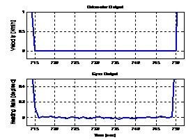
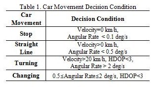
Ideally, odometer and gyroscope output is zero when the car is stopped. The stop area can be determined using this property. The raw odometer measurement is a pulse signal according to the rotation of wheel. For example, our odometer output is 4 pulses per one rotation of wheel. There are differences in true distance and odometer output and generally true distance is equal to or larger than distance from odometer. For this reason, we don’t know exactly when the car is stopped. Thus gyroscope angular rate is used to determine the more precise moment. When car was stopped, gyroscope outputs the zero-mean white Gaussian noise with very small variance. Figure 1 shows the odometer velocity and gyroscope angular (heading) rate when car was stopped. The stopped time is 715 sec from velocity and 716 sec from angular rate. From this figure, car stop moment can be decided more accurately through angular rate. We decide that the car stopped when odometer velocity was equal to zero and gyroscope angular rate was smaller than 0.1 deg/sec.
Fig. 1 Velocity and angular rate when car is stopped
Straight line
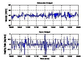
When car is moving in straight line, gyroscope outputs zero mean white noise with small variance. This variance is larger than stop area. When car is moving in straight line, the odometer and gyroscope outputs are represented in figure 2, respectively. The bottom figure shows that magnitude of angular rate is about 0.5 deg/sec. When odometer velocity is larger than zero and gyro angular rate is smaller than 0.5 deg/sec, we decided that the car is moving in a straight line.
Turning
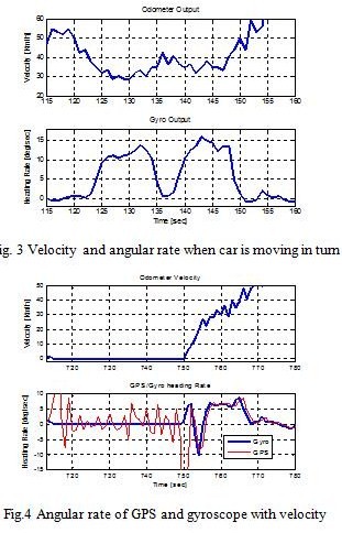
When car was in a turning area, gyroscope angular output has large value than other movement. We decide car is tuning if gyroscope angular rate is larger than 2 deg/sec. The threshold is determined through data analysis and figure 3 shows odometer and gyroscope output in turning area. To correct the gyroscope scale factor error in turning area, we use the GPS heading output as reference. When car is moving with low velocity, we cannot trust GPS heading output. Since GPS heading and velocity outputs are incorrect when vehicle is moving slowly. We determine the velocity threshold by comparing the GPS and gyroscope angular rate with velocity. Figure 4 represents the angular rate and velocity output. GPS heading output is similar with gyroscope when velocity is larger than 10 km/h. From this result, we determine the velocity threshold as 20 km/h. To confirm the availability we use GPS angular rate when HDOP (horizontal dilution of position) is larger than 3.
Fig. 2 Velocity and angular rate when car is moving in straight line
The car movement decision condition is represented in table 1. The changing area covers those cases other than the ones listed and when GPS data is available. In the changing area, we estimate the heading error than bias or scale factor error.
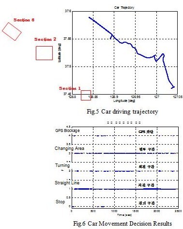
To verify the car movement decision condition, we apply to the real data and analyze the result. Figure 5 shows the overall car driving trajectory and test results are represented in figure 6~8. Figure 6 shows the overall decision results. Flag 0~4 mean the stop, straight line, turning, changing area and GPS blockage, respectably. Decision results in section 1 and section 2 in figure 5 are represented in figure 7~8 using Google map. In these figures, white line represents the cars moving trajectory and blue, yellow and red dot mean straight line, turning and stop. As shown in figure 7~8, decision condition can detect the car movement well.
Fig.8 Car Moving Decision Results in Section 2
GPS/DR Integration Algorithm
The basic and proposed GPS/DR integration system structure is represented in this section. The integration system designed is based on distributed kalman filter. Each filter model is explained with car movement decision condition.
GPS/DR integration system structure
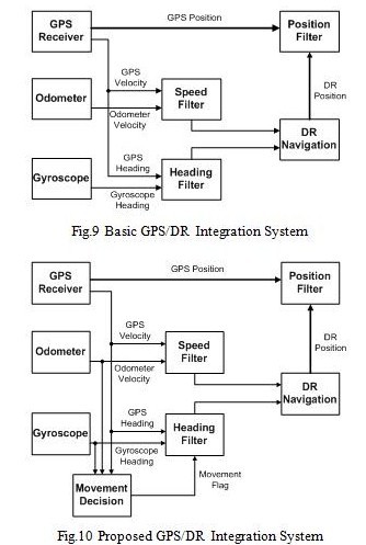
The integrated GPS/DR navigation system is composed of GPS receiver, odometer and gyroscope to obtain position, velocity and attitude of the vehicle, respectively. Figure 9 shows the block diagram of the basic car navigation system. As figure 9 shows, this system consists of three filters such as the velocity filter, the heading filter, and the position filter. The velocity filter and heading filter estimate the odometer and gyroscope error to correct the raw sensor data. These filter measurements are difference of GPS and DR sensor velocity and heading. The DR navigation algorithm generates the position of the vehicle by using estimates of the speed filter and the heading filter. From this information and GPS position information, the position filter gives an estimated position to the driver [10]. When GPS signal is blocked, DR sensor error cannot be estimated and corrected with this structure. Then position of integration system is diverged as time passes. To solve this problem, additional measurement is needed. In this paper, car movement information is used to correct the DR sensor data. The car movement information has smaller error than GPS heading or velocity in low velocity and straight line area. Figure 10 shows the proposed GPS/DR integration system block diagram. First, the current car movement information is decided using velocity and heading of GPS, odometer and gyroscope. Then heading filter measurement model is changed according to car movement. We can estimate the gyroscope error using this method when GPS signal is blocked or GPS measurement has large error. Each filter structure is explained in the following sections.
Heading filter
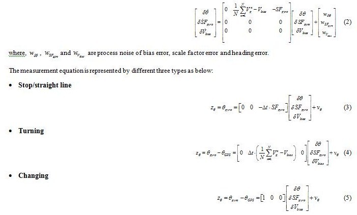
The objective of the heading filter is to estimate a heading angle error, bias error, and scale factor error of gyroscope by using GPS and car movement information. When the car is stopped or moving in a straight line, gyroscope bias error is estimated using car movement information, i.e., zero reference. The gyro scale factor error is estimated using GPS heading measurement in turning. In changing area, heading angle error is estimated. As above, the heading filter measurement model is changed according to car movement. The gyroscope error model equation is represented by
sample mean of output voltage and bias voltage is same. Then first term of equation (1) can be eliminated. In this case, heading error can be a function of bias error. When car is driving with turn, first term of equation (1) increases as heading angle is large. On the other hand, second term is maintained as a constant value. In this paper, three types of measurement models for heading filter are used with relationship between heading error equation and car movement. When car is stopped or driving in straight line, we use the bias error model. We use the scale factor error model if car is turning. Last, when car is driving in changing area, heading error model is used. The following are the heading filter equations
In stop and straight line area, measurement equation is same but we apply the different measurement noise.
Speed filter
The objective of the odometer filter is to estimate a scale factor error of odometer. From the compensated scale factor error, a velocity of vehicle is obtained. The scale factor error is modeled as random walk because a scale factor error of odometer does not change rapidly with time.
Position filter
The DR navigation algorithm calculates the vehicle position by using a velocity obtained from odometer and a heading angle obtained from gyroscope. The objective of the position filter is to estimate the vehicle position by using GPS and DR information. The following are the position filter equations:
Performance Analysis
Test environment
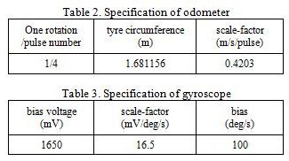
The integrated GPS-DR navigation consists of GPS receiver, odometer and gyroscope. The GPS receiver SiRFstarIII GSC3e/LP, which has ARM7TDMI processor of 50MHz and can track 20 GPS channels, is used. As table 2 shows, when the tyre circumference of vehicle is 1.681156m the odometer generates four pulses for one rotation of a tyre. So the scale-factor of odometer is 0.4203. The gyroscope XV-8000CB of EPSON TOYOCOM is also used. The specification of this is shown in Table 3.
To test the integrated GPS/DR navigation system, we consider the path where GPS signal is available. The figure 1 represents the overall driving trajectory of experiment. The results are analyzed in section 2 and section 3 in Figure 1. The section 2 is turn area and section 3 is straight line area, respectively. In these areas, we assume that GPS signal is blocked and analyze the results to compare with GPS solution. Last, the underground parking test results are shown.
Test results
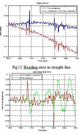
First, we analyze the straight line test results and these are represented in figure 11~14. Figure 11 shows the position result in Google map. In these figures, blue line represents the proposed system result and red line represents the basic system result. The white line means the cars true trajectory is obtained from GPS solution. The estimated position with car movement is more similar with true car trajectory. The position error is shown in figure 12.
The proposed system has 9 times smaller error than the basic system. Figure 13 shows estimated heading error. The basic system estimated heading error increases as time passes. In proposed system, gyroscope bias error is estimated using car movement information and heading error doesn’t increase. Figure 14 shows estimated gyroscope bias error. The green line means heading error is calculated using GPS and red line means heading error is calculated using car movement. Since the car is moving in a straight line, car movement correction result is more accurate than GPS correction results.
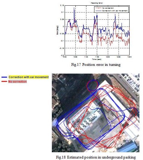
Next is turn area results and these are represented in figure 15~17. The proposed system result error is smaller than the basic system. In this case, proposed system error is also increased as time passes. Since bias, scale factor and heading error cannot be estimated in this section.
Finally, proposed system is tested in underground parking. Figure 17 shows estimated position of both systems. The car had been turned several times with same trajectory in underground parking. The proposed system estimated position has more regular trajectory than the basic system. For this reason, we cannot calculate the position and heading error since there are no reference solution.
Conclusions
This paper represents the GPS/DR car navigation system using vehicle moving information. GPS and DR sensor measurements are analyzed to decide the car movement. We implement the multi-measurement model for heading filter using this additional information. When GPS signal is blocked, gyroscope bias error is estimated using car movement information. A car experiment was performed to verify the proposed algorithm. The results show that the supposed method provides smaller position and heading error than previous method. When GPS is blocked in 300 sec, the position error is smaller than 9 times in straight line area and 3 times in turning area.
Acknowledgements
This research was supported by Industrial Strategic Technology Development Program, Development of a Cooperative Vehicle Control System for Accident Prone Areas, funded by the Ministry of Knowledge Economy (MKE, Korea).
References
[1] Jinwon Kim, Gyu-In Jee, and Jang Gyu Lee: Design of a Navigation System Using GPS and Dead-Reckoning, Vol. 2, No. 3, pp.188-193, 1996.
[2] Jae-Kuen Lee: GPS and DR Integration Technique for Car Navigation System, Master’s Dissertation, Konkuk University, 1997
[3] Dae Seon Park: Development of a GPS/DR Integrated Unmanned Ground Vehicle Navigation System Using Real Time OS, Master’s Dissertation, Konkuk University, 2000.
[4] Madhukar, B.R., Nayak, R.A., Ray, J.K., Shenoy, M.R., ”GPS-DR Integration Using Low Cost Sensors,” ION GPS 99, pp537-544, 1999.
[5] G. Dissanayake, S. Sukkarieh, E. Nebot, and H. Durrant-Whyte, “The aiding of a low-cost strapdown inertial measurement unit using vehicle model constraints for land vehicle applications,” IEEE Trans. Robot. Autom., vol. 17, no. 5, pp. 731–747, Oct. 2001.
[6] Shin. E. H..: Estimation Techniques for Low-Cost Inertial Navigation, Ph.D. Thesis, University of Calgary, 2005.
[7] S. Godha and E. Cannon: GPS/MEMS INS integrated system for navigation in urban areas, GPS Solution., vol. 11, no. 3, pp. 193–203, Jul. 2007.
[8] N. El-Sheimy and X. Niu: The promise of MEMS to the navigation community, InsideGNSS, vol. 2, no. 2, pp. 46–56, Mar./Apr. 2007.
[9] Itzik Klein, Sagi Filin, Tomer Toledo: Pseudo-Measurements as Aiding to INS during GPS Outages, ENC-GNSS 2009, May, 2009.
[10] Kwang-Hoon Kim, Jong-Hwa Song, Gyu-In Jee: GPS-DR Integration Navigation System for Car Navigation, 2009 International Symposium on GPS/GNSS, Oct., 2009.
My Coordinates |
EDITORIAL |
|
His Coordinates |
Dr Dru Smith Matthew M O’Connel |
|
Mark your calendar |
FEBRUARY 2011 TO AUGUST 2011 |
|
News |
INDUSTRY | LBS | GPS | GIS | REMOTE SENSING | GALILEO UPDATE |










 (No Ratings Yet)






Leave your response!