| GNSS | |
Joint Australian engineering satellite (JAESat)
JAESat is an Australian joint micro-satellite project between Queensland University of Technology, Australian Space Research Institute and other national and international partners, i.e. Australian Cooperative Research Centre for Satellite Systems, Kayser-Threde GmbH, Aerospace Concepts, Auspace to name some of them |
|
 |
|
|||||
|
||||||
 |
|
|||||
The JAESat mission will ultimately comprise two microsatellites called Master and Slave (see Figure 1) which will fly in a formation. JAESat Master and Slave will be separated in space, after the release of JAESat from the launcher.The mission is designed to conduct avariety of experiments based on the mode of interoperation between the payloads on-board the two satellites. A RF Inter-Satellite Link (ISL) for communication between the two satellites will be established. JAESat will be launched in 2007. The final orbit depends on the launch opportunity. It will have a circular, nearly polar orbit with an orbit height between 600 km and 800 km. The operational life time of JAESat is expected to be between 12 and 15 months. After the separation

of the slave from the master satellite the two satellites will drift away from each other with a low drift rate. JAESat is designed to have a high degree of on-board autonomy. The operations will be conducted via a ground station located at the Queensland University of Technology in Brisbane, Australia.
JAESat mission concept
The JAESat micro-satellite project is an educational and GNSS technology demonstration mission,
which will also generate data for scientific use. JAESat’s high level mission objectives are:
• design, develop, manufacture, test, launch and operate the educational/ research micro-satellite JAESat
• develop payloads with a technological and scientific relevance
• use JAESat as a sensor in space and GNSS technology demonstrator mission
The education and training aspects play an important role in the JAESat mission. The GNSS mission objectives are driven by the SPARx (SPace Applications GPS Receiver), a development from the Cooperative
Research Centre for Satellite Systems at the Queensland University of Technology. Functions
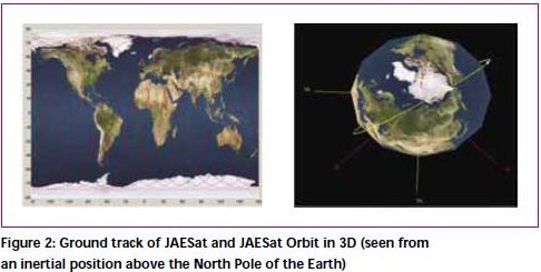
and performance of SPARx will be tested and validated in space within the JAESat mission. A key element of the GNSS activities will be the testing of a new sensor concept for attitude determination, based on Star Sensor and GPS based attitude information. In JAESat mission the master satellite will be a cube with a side length of 390mm. The slave satellite will have the following dimensions 390mm x 390mm x 195mm. The JAESat master satellite will be 3-axis stabilized, whereas the JAESat slave satellite will be gravity gradient stabilized. The mass of the slave satellite willbe around 10kg, and the mass of the master will be around 30 kg, so that the total mass of JAESat will be around 40 kg. The orbit of JAESat will be a Low Earth Orbit (LEO) with an altitude between 600 km and 800 km and an orbit inclination of around 90 deg. The ground track and the orbit in 3D space are outlined in Figure 2.
JAESat – Satellite system
The JAESat structure concept is based on a tray design. JAESat will have a total of eight trays. The separation between master and slave will be based on a spring release mechanism. The JAESat power system will consist of batteries and solar cells. Themaster satellite will have five sides covered with solar cells, whereas the slave will have only one side covered with solar cells. The slave will have a peak power of around 10 Watts. The available power at the master satellite will be around 25 Watts. The JAESat on-board flight computer will be an Intrinsyc CerfBoard. The JAESat communication concept is outlined in Figure 3.
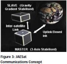
The transmitter module for the master communications system has been selected to be the Hamtronics TA451, operating at 400.400MHz. The modem is the Kantronics KPC-9612+. The receiver is the Hamtronics R451. It is a crystal based receiver operating at approximately 430MHz. The JAESat Attitude Control System (ACS) concept cannot be seen as one concept. The master satellite will be 3-axis stabilized by using magnet torquers (air coils). The slave satellite will be gravity gradient stabilized without using a boom. Instead the
moments of inertia will be designed so that a gravity gradient stabilization will be the result. After separation
from the launcher, the JAESat master and slave will still be attached to each other. JAESat master ACS will then reduce the rotation rates around each axis and fi nally orient the satellite in such an orientation that the slave will be in its gravity gradient orientation and then JAESat will split into two satellites. The ACS of the master will be used for controlling the orientation and changing of rotation rates, necessary for testing of the new integrated Star Sensor GPS attitude sensor concept. Only one requirement for the attitude accuracy
of the master has been derived, resulting from the need to have an Inter Satellite Link established.
The master attitude accuracy requirement is in the order of 5 deg.
JAESat – Payloads
The JAESat payloads concept is driven by simplicity. The payloads itself will be distributed between the JAESat master and slave satellite. One of the positive aspects of this distributed concept is that in the event of problems on one of the two satellites, or in the worst case scenario, the loss of the slave satellite, significant research can still be conducted. The JAESat master satellite will have
the following payloads on board:
• SPARx – GPS receiver capable of performing 3-axis Attitude Determination
• Star Sensor
• Specifi c antennas for atmospheric research
The JAESat slave satellite will have the following payloads on board:
• SPARx – GPS receiver
• Mini Video Camera (Web camera type)
• Specific antennas for atmospheric research
The CRCSS/QUT GPS SPARx (see Figure 4) development is based on the MITEL GP2021, GP2015 and GP2010 Chip set and is a modification of the MITEL Orion GPS receiver demonstrator. The base for the development of the source code is the MITEL GPS Architect development kit. The source code modifi cations are specifically targeted towards robust and accurate operation onboard a satellite. Key elements of
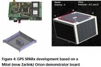
functionality are positioning and timing for satellites. Further R&D activities are the implementation of an on-board orbit determination capability (SPARx-OD) and GPS receiver modifi cations for satellite
attitude determination (SPARx-AD) capabilities. The JAESat master satellite will have a GPS receiver with
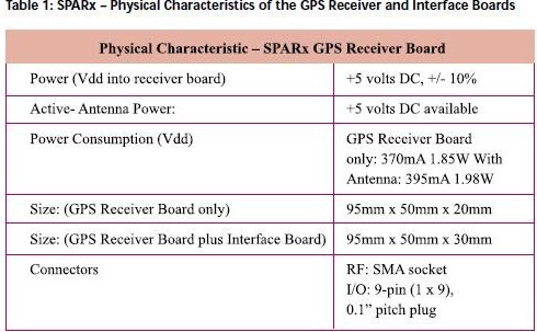
the capability of performing attitude determination. The on-board orbit – and attitude determination calculations will be performed within the Flight Computer. The main characteristics of a GPS SPARx are given in Table
1. In addition to orbit and attitude determination, it is also intended to perform relative navigation between
the JAESat master and slave satellite. Finally, SPARx will be used for collecting data from specific GPS antennas attached to the sides (looking to the horizon) of JAESat in order to perform atmospheric research.
Star Sensor – KM 1301
The Star Sensor KM-1303 is a contribution of the German Aerospace Company Kayser-Threde GmbH towards the JAESat project. This sensor is a low-cost single-package design for star tracking, star recognition, relative -and inertial attitude determination. The Star Sensor will be used for
testing of a new integrated attitude determination sensor concept.
JAESat – Experiments
The JAESat main experiments can be summarized as follows:
• Testing and evaluation of CRCSS/QUT GPS SPARx,including Attitude capability
• Testing of a new integrated Star Sensor/GPS navigation sensor concept for 3-axis attitude determination
• Relative Navigation between JAESat Master and Slave satellite
• Orbit determination concepts
• On-Ground – Precise orbit determination based on GPS Code and Carrier phase measurements
• On-board orbit determination based on GPS receiver position solutions
• Relative Positioning between master and slave satellite
• Establishment of stable RF inter satellite links
• Atmospheric research
JAESat operations
JAESat is designed for a high degree of on-board autonomy. However, the operations of JAESat will be conducted via a ground station located at the QUT in Brisbane, Australia.
Testing and simulations environment
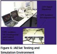
The core of the testing environment is the Welnavigat GPS signal simulator. The signal simulator is capable of
simulating the entire GPS satellite constellation and transmitting RF signals on six channels. The GPS
development platform (Architect Development Kit) is directly connected to the GPS signal generator and controlled/monitored from a notebook computer. An important feature in this context is the option to import
scenario files, generated by the user.
JAESat – Simulations and results
The results shown here are related to the expected performance of the SPARx in space, the position, velocity
and time solution, the capability of Orbit Determination (OD) and also the performance for the Attitude Determination (AD) based on GPS measurements. Test and simulations have been conducted with and without Hard Ware in the loop.
Results from GPS signal simulator and sparx
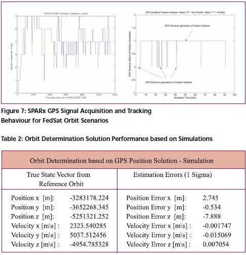
The main objective of these tests was to identify the GPS signal acquisition and tracking performance of SPARx. Results of tests conducted for JAESat including the GPS signal simulator and SPARx are given in Figure 7. In most cases SPARx generates a 3D position solution for more than 80% of the time per orbit. In this context it is also important to understand that the GPS signal simulator only provides a total of six simulated channels. This means that these tests can be seen as a kind of worst case scenarios. Another test objectives was also the testing of the time synchronisation performance and the generation of a Hard Ware Pulse Per Second (PPS) output. SPARx performance for a 3D absolute position solution in space is currently better than 20 m (1 Sigma).
Simulations for orbit and attitude determination based on GPS
Simulations for the Orbit -and Attitude Determination have been conducted.The results are presented in Table 2 and Figure 8. For the attitude simulations, the orientation of the antenna array was anti nadir. The baseline length was36 cm for baseline AB, AC and 51 cm for baseline AD. The multipath error was assumed to be 3mm on the carrier Single Difference (SD). The Orbit Determination concept is based on GPS
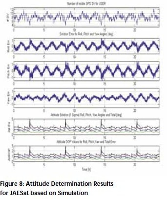
position solutions, used as observations in a batch Least Square process (Enderle et. al. 2003). A total data arc of 20 min. was used with a position solution every 10 sec and an assumed position error of 25 m (1 Sigma) for each x, y and z component of the position vector. The results in Table 2 show that a satellite on-board 3D position accuracy better than 10 m can be achieved with the proposed Orbit Determination concept. The results for the JAESat Attitude Determination (AD) based on GPS, presented in Figure 8 are highlighting that GPS based AD would already by sufficient to comply with the JAESat attitude accuracy
requirements. In Figure 8, it can also be clearly seen that the number of visible GPS satellites for JAESat lies between 4 SV and 12 SV with an average of 8 SV. This means a substantial higher number of visible GPS satellites for the JAESat as have been used for simulations with the GPS signal simulator.
Conclusions
The tests and simulations have clearly demonstrated the feasibility of the JAESat GNSS experiments in terms
of absolute positioning, timing, onboard orbit -and attitude determination. Further development and testing will be undertaken in order to cover the relative navigation aspects. Special emphasis will be given in the near
future for the testing of the integrated attitude sensor based on Star Sensor and GPS attitude information. Between 2003 and 2005 a total of 35 students have worked on the JAESat project
in various areas. This means that one of the high level mission objectives is
already fulfi lled – the use of JAESat as an education and research platform.
Acknowledgements
This work was carried out at CRCSS/QUT with the support of many partners. Special thanks to Kayser-Threde GmbH for the contribution of the Star Sensor, Intrinsyc for the CerfBoard, Aerospace Concepts and Cooperative Research Centre for Satellite System for the constant support and Solar Cells. Finally, I would like to mention all the QUT Aerospace Avionics Students and their valuable contributions to the JAESat project.
References
Enderle W., QUT – JAESat Project Documentation, JAESat– GPS – PO-0001, 2002
Enderle W., JAESat Mission Concept Description, QUT Project Documentation, 2004
Enderle W, Yanming F, Zhou N,Orbit Determination of FedSat based on GPS Receiver Position Solutions – First Results, Proceeding SatNav2003, Melbourne, Australia, 22–25 July 2003
Enderle W. Roberts P., GPS Receiver Development for Space Applications at Queensland University of Technology (QUT), Proceeding of the 10th Australian
International Aerospace Congress and 14th National Space Engineering Symposium, Brisbane, Australia, 29 July – 1 August 2003
Bruggemann T, Enderle W. Time Synchronization Capability of SPARx – the Queensland University of Technology (QUT) GPS Receivers, The 2004 International Symposium on GNSS/GPS, Sydney,Australia, 6–8 December 2004
MITEL Semiconductor, DS4605, GPS Architect 12 Channel GPS Development System,1997
My Coordinates |
EDITORIAL |
|
His Coordinates |
MAJOR GENERAL M GOPAL RAO, IRWIN ITZKOVITCH, CLEMENT
|
|
News |
INDUSTRY | GPS | GIS | REMOTE SENSING | GALILEO UPDATE |
|
Mark your calendar |
FEBRUARY 2006 to NOVEMBER 2006 |




 (No Ratings Yet)


Leave your response!