| Navigation | |
INS-GPS-GLONASS navigation fusion scheme for high dynamics guided projectiles
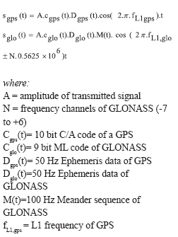
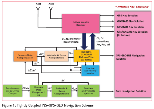
The Satellite Navigation solution is the most preferable, effective and economic aid to various Low and Medium Grade Inertial Sensors in order to get better Navigation accuracy for medium and long duration of navigation solutions. The navigation data from INS and Sat. Receiver at different intervals is synchronized and fused together by using Kalman Filter algorithm so as to obtain precise Navigation solution as long as Sat. Receiver tracks healthy and suffi cient number of Satellites constellation. The major limiting factor with the mostly used/popular GPS system performance is the availability of Satellites and the geometry of Satellites in view at any particular point in space and time. In order to alleviate this restriction for single constellation (i.e. GPS), it stands to reason that more observations to be introduced to provide increased levels of positioning continuity and higher levels of data redundancy. The recent enhancement of GLONASS satellite system suggests combined use with GPS, in order to increase the satellites availability as well as Navigation Solution continuity and accuracy. Taking the advantage of combined GPSGLONASS systems, the new Hybrid Navigation scheme has been developed to fuse the data from INS, GPS and GLONASS systems by using the raw measurements ( Pseudo ranges and Delta Pseudo-ranges) of GG Receiver and which are Synchronized to INS clock (Real-Time algorithms are adopted). The INS system is implemented in the strap down confi guration and the Extended Kalman fi lter is used to fuse the Inertial and GPS-GLONASS Raw measurements data in tightly coupled architecture. Integration of GPSGLONASS systemsThe GPS and GLONASS satellites transmit ranging signal and the ephemeris data at two different frequencies in the L-band. To our interest, L1 transmitting frequencies for both the systems are shown below. We can also state the transmitted C/A code signal on L1 frequencies from GPS and GLONASS satellites by following equations:
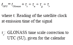
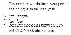
A combined GPS-GLONASS receiver can dramatically improve the reliability, visibility and productivity of positioning. However, the basic design differences of these system results in signifi cant complexity in terms of modeling and ambiguity resolution for integrated GPS and GLONASS positioning system. Two major differences between GPS and GLONASS that affect the combined positioning are given below. System time GLONASS system Time is closely coupled to Moscow time UTC SU (ICDGLONASS –2000). GLONASS system time is permanently monitored and adjusted in a way that the difference to UTC-SU does not exceed 100ns. It is closely coupled to UTC, but with a constant offset of three hours along with some leap seconds. Since there exist two different master clocks there is difference, which need to be accounted. GLONASS user is informed about the difference to UTC with parameter τc, as a part of GLONASS ephemeris .In order to combine GLONASS and GPS the different system time scales must be taken into consideration such that we obtain a unique time for all observation. Transformation from GLONASS time to GPS time can be done with the help of following equation.
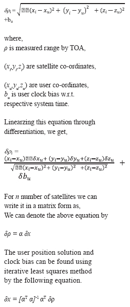
Co-ordinate frames In GLONASS only solutions, satellite positions in PZ-90 are obtained from the ephemeris data, thus the user position is in PZ-90. In GPS only positioning solutions, the satellite positions are given in WGS84 and thus the user position is in WGS84. Since GPS navigation has become the standard in Western countries and WGS84 therefore is more widely spread and better known than PZ-90, it is considered best to transform GLONASS satellite positions from PZ-90 to WGS84, thus obtaining the user position also in WGS84. There are several transform available, fi gure below shows one of the most commonly used transform. The combination of GLONASS and GPS nearly doubles the number of available satellites. This will increase the effectiveness of some applications, e.g., Real-time Kinematics’ (RTK) and troposphere estimates. The usage of two autonomous systems should also improve the reliability. As we saw above that in order to combine GLONASS and GPS • a unique time scale for all observations and satellite ephemerides and • a unique reference system for all satellite and receiver positions are required. Combined positioning In GPS or GLONASS system, as you know there are four unknowns and more than four observables available. The measurement can be mathematically represented as, Two tracking loops are needed to track Navigation Satellites signal. One tracking loop is for Carrier Doppler removal and another is Code tracking loop for phase error elimination. Doppler frequency from carrier tracking loop can be aided to the code tracking loop. The loop consists of prediction integrators, a discriminator and a loop fi lter. Prediction integrator reduces the noise by integrating the correlation value for a given time. As the integration time increases, the noise performance improves, but the dynamics performance becomes weak. Beyond certain high dynamics the single mode FLL is the preferred carrier tracking loop to track the Satellites signal than FLL assisted PLL Loop. Single mode leads to a marginal tradeoff between accuracy and tracking of the signal beyond certain high dynamics. In our receiver design third order FLL loop has been adopted in order to successfully track the GPS-GLONASS Satellites signal for High Dynamics Projectiles applications. Tightly coupled INS-GPSGLONASS fusion scheme
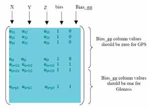
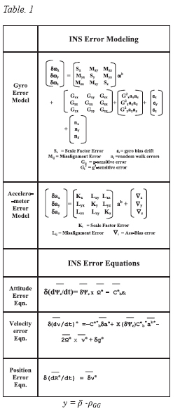
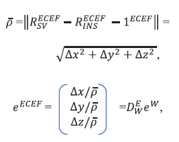
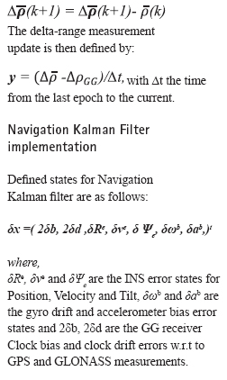
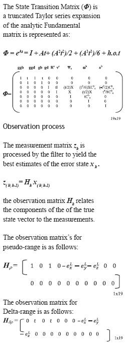
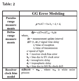
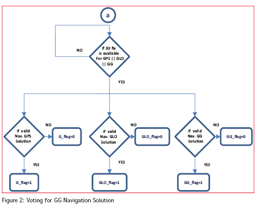
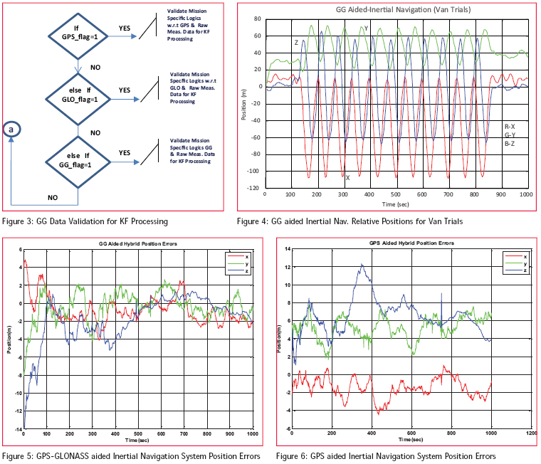
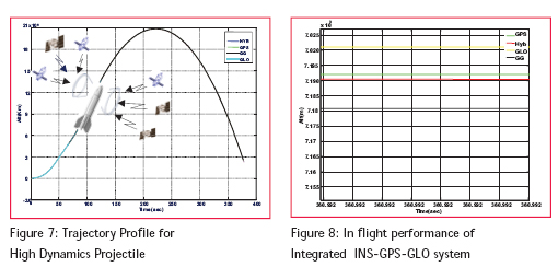
The tightly coupled filter requires line of sight information to the satellites as well as potential information on GG signal strength or elevation angle to improve the measurement noise estimates while incorporating the GPS and GLONASS updates. Apart from characterizing the measurement errors to design the measurements matrix R (for Pr & DPr) the KF does Estimates Clock Bias and Clock Drift errors of Receiver clock in order to correct the Clock Bias and Clock Drift Models (as shown in Table 2) so as to compute true Range and Delta-Range. Before processing the pseudo-range measurement update, an estimate of range to the satellite from the INS i.e. is computed with INS position estimate and the Line-of-Sight vectors to the satellites as shown below: The delta-range measurement update is then defi ned by: with Δt the time from the last epoch to the current. In the observation matrixes the fi rst two elements represent the GPS clock bias and clock drift observations. The next two elements are the GLONASS clock bias and clock drift observations. The Measurement noise values for Pr & Dpr are 2 m and 0.02 m/s respectively. Voting for multiple GG navigation solutions and receiver data validation for KF The fusion Filter is driven by number of Navigation solutions available with GG receiver. Therefore it becomes obvious to take best decision in Real time to get optimized Hybrid Navigation solution so as to guide the Vehicle in the desired basket of accuracy. INS-GPS-GLONASS Scheme PerformanceThe performance of the GPS-GLONASS aided Inertial Navigation systems are evaluated for Real Time in the Lab as well as for the simulated Flight trajectories of various High Dynamics Projectiles. This study has been carried out using different class of Inertial Sensors ranging from Medium Grade to High Grade accuracy. The Navigation fi lter was tuned for different application by adjusting noise spectral densities in order to achieve acceptable fi lter performance for Low and High Dynamics applications. Figure 4 & 6 shows the Medium Grade Dynamically Tuned Gyros based INS-GG System performance ( for static and Low Dynamics). As analyzed, where the INS is aided by single ( GPS/GLO ) constellation, the position error of Hybrid Navigation is driven down to less than 15m (1-σ) after about 50 sec, whereas the position error of combined aided GPS-GLONASS constellations is better than 7m (1-σ) after 50 sec as shown in fi gure 5. It has been observed that for weak GPS constellation the concurrent healthy GLONASS measurements provides better accuracy, high redundancy and more reliable combined GG solution. This also results in improved GDOP and Hybrid Navigation Performance. Further the Real Time Simulation studies are carried to analyze the performance of this scheme for High Velocity Projectile applications. The scheme has been simulated for medium range guided Projectile and post simulation results were analyzed as shown in fi g 7 & fi g 8. The Projectile travelled with forward velocity 800m/s and beyond covers the short (< 100 Km) to medium down range (< 250 Km) in the fl ight time of 371 sec. As it’s analyzed, the Vehicle in the entire Thrust Phase and beyond is guided through either by GPS or GG aided Navigation by correcting all the propagated Navigation errors in all phases, which resulted in achieving the desired accuracy for Hybrid Navigation (< 25 m, 1-σ) of the Vehicle as shown in fig 8. |
My Coordinates |
EDITORIAL |
|
Mark your calendar |
August 2012 To June 2013 |
|
Conference |
GNSS: Agenda and approach |
|
News |
INDUSTRY | LBS | GNSS | GIS | IMAGING | GALILEO UPDATE |




 (3 votes, average: 3.00 out of 5)


Leave your response!