| Surveying | |
GPR data georeferencing using photogrammetry and digital maps
This paper presents the first results of a feasibility study of a system where photogrammetry, digital maps and GPS are combined to georeference GPR surveys |
|
Ground Penetrating Radar (GPR) provides a picture of the different materials or structures underground up to a few meters of depth. To provide a 3D map of underground objects such as pipelines, the georeferencing horizontal tolerance should be around 20 cm, a figure achievable by GNSS systems. The conditions of GPR urban surveys, though, make it impossible to rely on GPS alone for positioning. In front of large blocks, in narrow streets, or in tree-lined avenues GPS is not sufficient to guarantee uninterrupted coverage. To overcome the problem, systems combining GPS and inertial navigation can be used (Zhang et al., 2005) although rather expensive. Another possibility is to use photogrammetry to georeference the GPR trailer. This paper presents the first results of a feasibility study of a system where photogrammetry, digital maps and GPS are combined to georeference GPR surveys.
Georeferencing by photogrammetry
The GPR-trailer will host at least a pair of reflex digital medium resolution cameras, installed on a rigid frame, high enough to minimize occlusions by parked cars and looking leftwards and rightwards; each will acquire a strip of the building façades at the side. A GPS antenna will be mounted on the top of the frame. Data acquisition from the different sensors will be synchronized, in order to allow time interpolation of the trajectory; cameras will be triggered by an odometer; calibration will account for lever arms and misalignments between the sensors.
Tie points along each strip will be automatically extracted and matched by a robust Structure and Motion algorithm (Pilu, 1997; Fischler and Bolles, 1981; Hartley and Zisserman, 2000; Forlani, Roncella, Remondino, 2005). Using calibrated cameras, the orientation of each pair in an arbitrary metric frame can be recovered through the essential matrix; approximate point coordinates can be computed by forward intersection using a linear algorithm. By alternating intersection and resection, each strip will be oriented in an arbitrary frame.
Maps standards prescribe a 95% tolerance of 40 cm for 1:1000 scale (Blachut et al., 1979): therefore map points may be used as GCPs to georeference the photogrammetric strip. Full (3D) GCPs can be easily recognized and measured on the images at building block corners (at ground level); 2D GCPs can also be measured along vertical edges of a building.
Since the accuracy of the perspective centres decreases along the strip with the distance from the closest GCP, the relative orientation (RO) and the distance between left and right cameras, known by calibration, can be enforced, to constrain the solution.
A final bundle adjustment will provide the projection centres of the images, combining the available information: the GCP coordinates, the relative orientation constraint, any available GPS position.
As long as the camera records building façades, tie points will be extracted and matched seamlessly, because of the rich texture and optimal viewing geometry. When crossing large roads or squares, though, finding tie points is difficult. If the GPS position is available, no photogrammetric solution is necessary; otherwise manual measurements must be used to improve tie point distribution.
Simulations
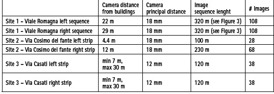
In order to verify the accuracy of the positioning in different conditions, simulations have been performed. The test area is Milan (Italy), where a recent city base map at 1:1000 scale is available (Bezoari et al., 2005).The simulation characteristics are:
– 3D scene set up using the City Base Map;
– tie points on buildings distributed on a grid with 4 m spacing;
– some tie points on the ground, located on large crossroads;
– a full GCP at every building corner (at ground level);
– 6 Mpixel camera with 18 o 12 mm lens;
– acquisition of a synchronous image pair every 3 m;
– tie points measurement accuracy = 1 pixel.
For trajectories close to building face, short focal lengths and camera axis tilt (from –3° to +9°) were used to get more coverage of the building façade on the images. Exposure time must avoid image blurring due to motion, a possible limiting factor for the operating speed in narrow streets.
Since in most buildings the demarcation between floors is clearly distinguishable, it has been assumed that one horizontal point can be measured at every floor along a building vertical edge. Eaves, although in principle all suitable as height points, are seldom imaged: in a single strip therefore the height points will be located only at ground level, often quite aligned. In this case, the rotation of the whole strip along an axis parallel to camera trajectory is not controlled by the GCPs, yielding large uncertainties for rotations and elevations of the camera centres. Running two opposite-looking strips and enforcing the relative orientation reduces the problem, although not completely.
The accuracy of the camera projection centres has been computed by error propagation from the image coordinate errors. Three test cases will be described:
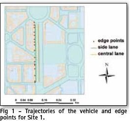
Site 1 – Viale Romagna (Figure 1):
▪ Road width = 50 m;
▪ blocks about 100 m long;
▪ two road crossings (23 and 31 m large).
Site 2 – Via Cosimo del Fante:
▪ Road width = 16 m;
▪ one block about 230 m long.
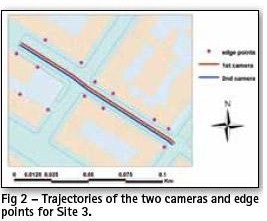
Site 3 – Via Felice Casati (Figure 2):
▪ two different road widths: about 19 m and about 12 m.
In each site five different block configurations (2sA, 2sB, 2sC, 1sA, 1sC) have been simulated varying:
▪ number of strips used: 2s: both left and right; 1s: only right
▪ ground control:
○○A: 4 full GCP, two per strip, at ground level, at the strip ends;
○○B: same as A plus 4 horizontal GCP (one on the same vertical building edge as the full GCP);
○○C: 1 full GCP at ground level at each building corner plus an horizontal GCP on the same vertical building edges.
When both strips are used, the relative orientation (RO) from the left and right synchronous images is always enforced (this allows also to use the otherwise rank-deficient ground control of case A).
Results
Site 1 – Viale Romagna
Although these figures seem to depict a strong block (the redundancy ratio is larger than 4) in fact the height GCP is poor, unless also points on building eaves can be measured.
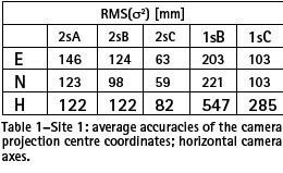
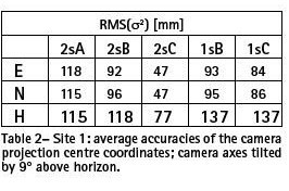
Table 1 summarizes the results: for each coordinate of the camera projection centres, the RMS value of the variances computed from error propagation are shown.
It is apparent that, with the same GCP, combining the two strips increase the overall accuracy of the projection centres.
Horizontal accuracy requirements can be met with sufficiently dense GCP. The accuracy of the attitude angles is quite large for omega and kappa: more than 13° even in the best case, because a too little area of the image format is covered by tie points. By tilting the camera axis above the horizon by 9° the results are significantly better in terms of attitude (0.2°) and in (E, N) while the elevation accuracy does not change very much, at least for the two strips (see table 2).
Site 2 – Via Cosimo del Fante
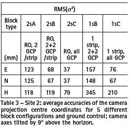
In this case, though, GCP B and C actually coincide, since there are no other GCP except at the block ends. Results in table 3 for the single strip refer to the right strip only. The accuracy figures with respect to the other sites are less good, because of the sparse GCPs. It is interesting to notice that, even if one strip is somehow fragmented in patches, it still helps to make the block more stable, especially in elevation but also in horizontal: this was not the case in the other sites.
Site 3 – Via Casati
Block relative redundancy is 3.1; on average, there are 11 pts/ photo and 3.6 rays/pt.
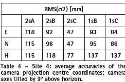
When both strips are used, the RO from left and right synchronous images is always enforced (see table 4). With respect to Site 1, the accuracy figures show that the shorter average distance of GCP partly compensates for the smaller number of tie points per image and rays per point. A shorter focal of 12 mm is necessary, due to the closeness to the building façades. As in Site 1, with all GCP, the gain in accuracy when using both strips is about 100%.
Conclusions and perspectives
The results obtained from this three simulations suggest that the objective can be achieved, provided that GCP can be recognized on images at intervals not much larger than 200- 250 m, with precisions below 10 cm. Preliminary tests with real image sequences show that automatic image orientation can deal with sequences of 30-40 images without problems.
Before moving to an implementation stage of the method, optimization of several system components and surveying parameters is though still needed.
Acknowledgements
The authors wish to thank the Milan Municipality and the Province of Milan for the City Base Map.
References
Barzaghi R., Carrion D., Cazzaniga N. E., Forlani G. (2009), Vehicle positioning in urban areas using photogrammetry and digital maps, Proceedings of ENC-GNSS09, Naples.
Bezoari G., Monti C., Selvini A. (2005), La cartografia numerica della città di Milano: interventi per il collaudo, Rivista dell’agenzia del Territorio, 2/2005, pp. 58-76.
Blachut T.J., Chrzanowski A., Saastamoinen J.H., (1979), Urban Surveying and Mapping, Springer-Verlag, New York.
Fischler M., Bolles R. (1981), Random sample consensus: a paradigm for model fitting with application to image analysis and automated cartography, Commun. Assoc. Comp. Mach., Vol. 24(3), pp. 81-95.
Forlani G., Roncella R., Remondino F. (2005) Structure and motion reconstruction of short mobile mapping image sequences, Proc. of the 7th Conf. On Optical 3D measurement techniques, Vienna, 3-5 Oct. 2005, Vichman Verlag, Vol I, pp. 265-274.
Hartley R., Zisserman A. (2000), Multiple View Geometry in computer vision. Cambridge University Press.
Hofmann-Wellenhof B., Lichtenegger H., Collins J. (2001), GPS – Theory and Practice, Springer, Wien.
Kim S., Choi K., Lee S., Choi J., Hwang T., Jang B., Lee J. (2004), A Bimodal Approach for Land Vehicle Localization, ETRI Journal, Vol. 26(5), pp. 497-500.
Pilu M. (1997), Uncalibrated stereo correspondences by SVD, Proc. CVPR , pp. 261-266.
Zhang H., Petovello M.G., Cannon M.E. (2005), Performance Comparison of Kinematic GPS Integrated with Different Tactical Level IMUs. CDROM Proc. of NTM 2005, San Diego, The Institute of Navigation.
 |
|
||||
 |
|
||||
 |
|
|||||
 |
|
||||||
My Coordinates |
EDITORIAL |
|
His Coordinates |
John Pottle, V P Agrawal, Shri KR Sridhara Murthi |
|
News |
INDUSTRY | GPS | GALILEO UPDATE | LBS | GIS | REMOTE SENSING |
|
Mark your calendar |
AUGUST 2010 TO NOVEMBER 2011 |




 (1 votes, average: 1.00 out of 5)


Leave your response!