| Mycoordinates | |
Measurement of deflection of a bridge
|
||||||||||||
|
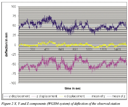
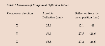
Engineering structures undergo deformation due to various kinds of static and dynamic loads. Thus, monitoring of structure, specifically large structures such as high-rise building, bridges, dams etc., is essential to ensure its safe deformation behavior. With multifold rise of traffic, to provide safety and to prevent disaster, it has become necessary to detect uncharacteristic deflections and vibrations of bridges. The instruments which are often used for measurement of defl ection such as Global Positioning system (GPS) provides the position of a point easily, quickly and very precisely in a predetermined co-ordinate system (WGS84). Observation in relative GPS positioning has been found to be a viable tool for monitoring the defl ections of structure with real time capabilities. A detail investigation towards the viability of GPS system for measurement of deflection in a bridge is going on. An experimental observation followed by preliminary study has been carried out for a suspension bridge, as a part of detail investigation and the same has been reported. Cable-Stayed Bridge at RoorkeeThe Cable-Stayed Bridge at Roorkee is situated over upper Ganga Canal near Irrigation Research Institute Roorkee (Figure 1). It provides a convenient way for pedestrians and bicycle riders to cross the canal. It is trussed structure having span of about 30 meters. It has two pylons, one at either bank of the canal. The experiment was carried out to determine the defl ection of a point near the mid-span of bridge where defl ection is most perceptible. GPS observation and ResultsFigure 1 shows the location of the GPS station near the midspan of the IRI bridge. Two GPS receivers have been used in this experiment. One of them, served as reference, was placed on the roof of Geomatics Engineering section of Civil Engineering Department of IIT Roorkee. The other one (rover receiver) was placed over the point of observation i.e. near the midspan of bridge, which is about 1.3 kilometer away from the reference station. The observations were recorded at 1 Hz sampling rate on both L1 and L2 frequencies in a single session of about 25 minutes. While reference receiver collected data in static mode, rover receiver collected data in kinematic mode. The carrier phase raw data from both L1 and L2 frequencies were processed using Leica SKI 2.3 software. Ambiguities were resolved at each epoch by applying stringent constraints on the approximate coordinate of the unknown point. The epoch-byepoch ambiguity fixed solutions in Cartesian WGS84 X, Y and Z components of deflection of the observed point are as shown in Figure 2. It can be noted that deflection in X direction is much less severe than that of Y and Z- direction. The spikes in all the three components can be attributed to the displacement of the observation station due to passing pedestrian or cycle riders. It can be noted the amount of component of deflections were increasing gradually and then decreasing once they reached maximum. These were due to the dynamic action of load which gradually approached towards and then gradually moved away from, the observation station. The amount of absolute values of deflection components along the Cartesian WGS84 X, Y and Z directions and their maximum deviation from mean position are shown in Table 1. It can be found that deflection components having precision in sub-millimeter range were measured from GPS observation. ConclusionThe results from preliminary investigation show encouraging outcome for carrying out the detail investigation of the work. As GPS observations are associated with some inherent errors, the raw data will be preprocessed fi rst before utilizing the data during further investigation. In order to improve the precision of positioning, processing will be carried out using scientifi c software in detailed investigation. As most structure has their inherent natural response, to find the absolute value of deflection of bridge under dynamic load the natural frequency component will be detected and removed in further investigation. Moreover, to find the defl ection components in field condition the WGS84 coordinates will be transformed to bridge coordinate system. Further, to ensure the reliability of the measurements using GPS, deflections will also be measured and then compared with those conventional methodology. Thus, efforts are on to ensure that GPS is a reliable instrument for maintenance and real time monitoring of bridges. Reference:1. Maria Tsakiri, , Vassilis Lekidis, Mike Stewart and John Karabelas “Testing procedures for the monitoring of seismic induced vibrations on a cable stayed highway bridge.” 2. Roberts, G.W., A.H.Dodson, and V.Ashkenazi, Twist and Deflection: Monitoring Motion of Humber Bridge, GPS World, 10(10),1999. 3. Roberts, G.W., X. Meng and A.H.Dodson, Structural Dynamic and Defl ection Monitoring using integrated GPS and Triaxial accelerometers, in ION GPS’2000, 13th International Technical Meeting of the Satellite Division of the Institute of Navigation, September 2000, Salt Lake City, USA. 4. Roberts, G.W., X. Meng and A.H.Dodson, Data Processing and Multipath Mitigation for GPS/ Accelerometer Based Hybrid Structural Defl ection Monitoring System, in Proceedings of ION GPS 2001, 14th international Technical Meeting of the Satellite Division of the Institute of Navigation, September 2001, Salt Lake City, USA. 5. Meng, X., G.W. Roberts, A.H.Dodson, E. Cosser, C.Noakes, Simulation of the Effects of Introducing Psuedolite Data into Bridge Deflection Monitoring data in the Proceedings of the 2nd Symposium on Geodesy in Geotechnical and Structural Engineeing. |
||||||||||||
|
||||||||||||
|


 (1 votes, average: 4.00 out of 5)


