| Applications | |
2D-based indoor mobile laser scanning for construction digital mapping application
This paper aims to introduce an innovative laser scanning method for indoor construction mapping |
 |
|
 |
|
 |
|
 |
|
 |
|
 |
|
Various 3D imaging techniques have been developed during the past few decades in order to meet the increasing requirements of industrial and social applications (U.S. General Services Administration, 2009). These techniques are able to measure or capture existing conditions in a natural or built environment, and then present them in 3D images for modelling aims. The generated 3D models are widely used for urban planning, landscape design, topographic analysis, environmental management, simulation of construction, disaster forecast, etc (Bosché, 2010). A valuable application of 3D imaging for architectural, engineering and construction (AEC) industry is the asbuilt quality control from construction mapping (Akinci, et al., 2006). As a wellknown modern imaging technique, laser scanning (also known as light detection and ranging (LiDAR)) is developed for geospatial mapping and surveying (Klein, et al., 2011). The benefits it brings such as increased accuracy, reduced errors and rework, shortened schedule, improved quality control, 3D visualization and spatial analysis, make it appropriate for the civil and built environmental applications, particularly for indoor mapping and construction quality control.
However, conventional laser scanning technologies such as terrestrial laser scanning (TLS) and aerial laser scanning (ALS) although can provide very high measurement accuracy and large measurement ranges, their applications are constrained by high capital costs, site scale limitations, complex preparations and long duration (Fryskowska, et al., 2015; Kedzierski, et al., 2014). Therefore, this paper will propose a novel 2D-based indoor mobile laser scanning method for construction digital mapping.
This method integrates an IMU-GPS (Inertial Measurement Unit – Global Positioning System) positioning system with a portable and low-cost 2D laser scanner to realize 3D indoor mapping for an existing building room (Lee, et al., 2016). Then the mapping results are compared with the 3D design model of the building room, which is created by using Building Information Modelling (BIM). This comparison can help stakeholders to find out the discrepancies between existing construction and design model. Furthermore, it also gives a fast 3D mapping for real-time building indoor conditions to realize time-saving and cost-saving applications.
Literature review
Mobile laser scanning (MLS) is attracting more and more concerns due to its flexibility and mobility compared with TLS (Thomson, et al., 2013). Relevant concepts about mobile mapping systems were announced in the late 1980s and early 1990s (Barber, et al., 2008). Initially a 3D laser scanner was mounted on vehicles to rapidly capture information from existing natural or built environment. Nowadays portable and small-sized laser scanners are developed in order to bring users more convenience and make access into narrow and limited sites, such as corridors and roofs (Fryskowska, et al., 2015). Although the accuracy of MLS is lower than that of TLS, the benefits of cost and time saving brought by MLS still make it competitive. Currently, laser scanning is not only used for exterior mapping and surveying, but also considered for indoor application (Thomson, et al., 2013). TLS can be used for indoor quality control of as-built constructions. Combined with the technical assistance from ALS, the 3D presentations of building interior and exterior scenes can be implemented through the data integration of both laser scanning technologies (Kedzierski, et al., 2014).
Currently, for the AEC industry, 3D point clouds obtained from laser scanning usually are used for two main applications: quality control of as-built constructions and restoration of existing buildings (Alomari, et al., 2016). The point clouds which capture the real conditions of as-built or existing buildings and built environments are compared with their 3D design models through intermediary tools. The building design models are created and exported from BIM software, such as Autodesk Revit. BIM is an emerging technology for AEC industry in recent years. It is not only a 3D modelling tool, but also an innovative way to realize 3D visualization and multi-dimensional simulation for building project lifecycle from planning stage to operation and maintenance phase (Eastman, et al., 2011). Compared with traditional CAD (Computer Aided Design), BIM brings lots of benefits for construction projects, such as design optimization, clash detection, multi-disciplinary collaboration, time and cost savings (Eastman, et al., 2011). Its integration with laser scanning can help find out discrepancies between as-built constructions and corresponding design models (Alomari, et al., 2016). Furthermore, the 3D information captured from laser scanning is able to help implement the indoor mapping and scene restoration of existing buildings and built environments (Bassier, et al., 2016). Based on the real captured data and BIM 3D modelling, stakeholders can make a repair or retrofit plan for existing buildings, particularly for those historical constructions.
However, there are still some challenges which constrain the applications of conventional 3D laser scanning. From the technical aspect, the pre-work for 3D terrestrial laser scanning such as target assignment is tedious and its quality can influence the scanning results. In addition, users need to register and process the collected 3D datasets into point clouds by using bundled software after scanning. This step is time-consuming and the quality of 3D point clouds can be impacted by manual operation errors if users are not trained to a certain level (Hong, et al., 2015). Although Simultaneous Location and Mapping (SLAM) has been proposed in recent years to overcome the defects mentioned above, but due to the technical problems such as nonlinearity and incorrect association between observation and landmark (Thomson et al., 2013). From the economic aspect, the capital expense of a high-performance 3D laser scanner and bundled software is costly, people who intend to use this technique and meanwhile have budget control will consider this inevitably.
Methodology
To maintain the advantages of MLS and eliminate the barriers of conventional 3D laser scanning mentioned above, a novel indoor mobile laser scanning method is proposed. This method combines a 2D laser scanner with an IMU-GPS positioning approach to realize 3D indoor mapping. Different from the point clouds which are registered and generated from captured 3D raw datasets, this method integrates 2D scan images with the motion trajectory of the laser scanner in order to create 3D imaging for existing environments.
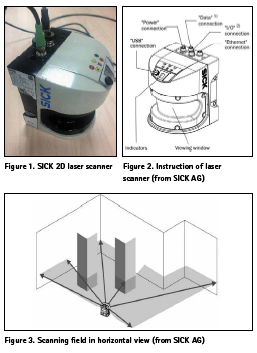
In this research, a SICK 2D laser scanner is used and the type is an LMS5xx LiDAR sensor that uses 905nm infrared as the light source (shown in Figure 1) (SICK AG., 2017). Compared with 3D laser scanners, it has much lighter weight and smaller size. Of course, the expense of this 2D laser scanner is also much cheaper. In addition, it has an operating range from 0-80m with high resolution and an aperture angle of 190o (view setting from -5o to 185o) (SICK AG., 2017). If the viewing window of the 2D laser scanner is kept horizontally as shown in Figure 2, the scanning field will display as Figure 3 shows.
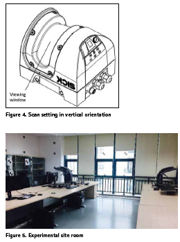
As our research aim is to integrate 2D scan images with a trajectory acquired from IMU-GPS positioning system for 3D mapping, the viewing window of the laser scanner should be kept vertically as shown in Figure 4. Therefore, 2D scan images are presented in X and Z (or Y and Z) axes and the motion trajectory of the laser scanner is shown in Y (or X) axis.
To determine the motion trajectory of the laser scanner, an IMUGPS positioning system was proposed for this research (Stephen, et al., 2006). This positioning system consists of a strap-down IMU and a GPS module. However, GPS is not available for indoor positioning due to the signals will be obstructed by building fabrics such as walls and ceilings. Therefore, IMU was adopted in this research to predict reliable motion trajectory information and fill the vacancy of GPS signal outages (Klein, et al., 2011). Typical IMUs consist of three-axial accelerometers, three-axial gyroscopes and magnetometers. The accelerometers is used to measure the accelerations of the object in x, y and z axes and the gyroscopes are used to measure the angular rate (the rate of turn) of the object in roll, pitch and yaw axes (Stephen, et al., 2006). By integrating the acquired threeaxial accelerations, it is able to obtain the velocity of the object which the IMU is mounted on and integrating the velocity again, the displacement of the object is calculated. Magnetometers are used to prevent the orientation errors by utilizing the magnetic north as a reference (Hellmers, et al., 2014).
For this research, IMU is an appropriate option due to its lowcost, small sized and low energy consuming characteristics (Klein, et al., 2011). However, it can only give accurate predictions in a short term and the errors will accumulate over time. That means the measurement accuracy cannot be guaranteed in a long-term application. Therefore, the positioning results were calibrated by using filters during the data processing.
In addition, it is also crucial to realize time synchronization between the IMU-GPS system and the laser scanner. Because each position of the motion trajectory should be mapped to the corresponding 2D scan image which is generated by laser scanner at the same time. After the synchronized scan and positioning experiment, all the collected raw data will be processed through a MATLAB-based algorithm.
Experiment
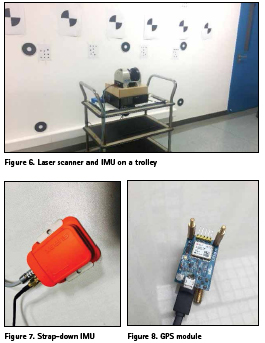
During the experiment, a computer room was used as the site (shown in Figure 5). The laser scanner and IMU were mounted on a trolley (shown in Figure 6), which was driven in an approximate linear motion from north to south and east to west. Then both laser scanner and a strap-down IMU (shown in Figure 7) were connected with a laptop by wires. The laptop was used to observe the scan profile and the IMU measurements. In addition, a GPS module was also connected with the laptop in order to synchronize the setting time of laptop with GPS time (shown in Figure 8). As IMU has its own measurement time record and the laser scanner uses laptop time, it is necessary to synchronize the IMU measurement time with laser scanning time by using the common GPS time. Although the experimental site was indoor, the GPS time was maintained continuously when we moved the module and laptop from outdoors into the room.
First the scan was implemented from the northern side of the room to the southern side by trying to keep the trolley in an approximate linear motion, then this was again from the eastern side to the western side. Meanwhile, the relative positions of the 2D laser scanner and the IMU were maintained in order to eliminate the errors caused by relative displacement. This can be realized by fixing the centers of both devices on a vertical shaft. As the vertical elevation difference between the viewing window and the ground was 0.7m, the scan results would only show the profile images above this elevation.
Result analysis
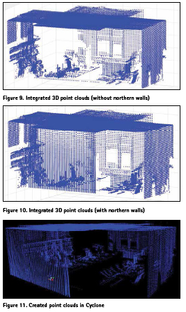
The 2D scan results were displayed and saved by using the SOPAS Engineering Tool, which is a bundled support software for SICK laser scanners. The main parameter values including 2D axial coordinates and intensity were extracted from the acquired scan results through a MATLAB-based algorithm. For the motion trajectory, a step length and heading estimation based on Pedestrian Dead- Reckoning (PDR) algorithm was applied in order to determine relatively accurate positions of laser scanner at each time interval point (the time interval was 1 second) (Kang, et al., 2012; Ruiz, 2017). Then each position was matched with the corresponding scan data at the same time point. Eventually, when all the extracted scan results were combined with the positioning trajectory measurements, 3D point clouds were formed as shown in Figure 9 and Figure 10. Here the quality of produced 3D point clouds depends on the combination level of 2D scan data with positioning trajectory and the accuracy of positioning measurements (Randall, 2011).
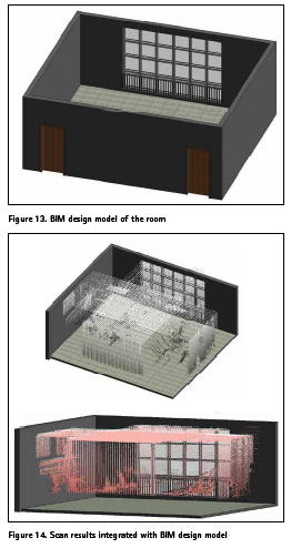
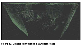
The next step is to import the scan point clouds into BIM tools. The objective of this step is to realize the integration of real site conditions with BIM design models for indoor mapping and discrepancy inspection. In this research, Cyclone and Autodesk Recap were used to implement the import of point clouds into Autodesk Revit (Tang, et al., 2010). Figure 11 and Figure 12 respectively display the processed point clouds in Cyclone and Recap. Figure 13 shows the initial BIM design model of the computer room, which was created in Revit before.
After the integration, it can be seen from Figure 14 that the indoor conditions above the ground 0.7m are almost reproduced (except the corners), and the scan profiles of room elements including windows, walls and ceiling, roughly match their dimensions in the BIM design model. However, there are still some discrepancies between the scan results and the design. These discrepancies may result from the errors which occurred during the experiment and later data processing, or the alterations in the actual construction phase of the room.
Outlook
For this research, although the experimental results indicate that the IMU-GPS system is applicable for indoor positioning, other advanced localization methods need to be experimented as they may highly improve the positioning accuracy and minimize measurement errors, even if the cost will also rise. Ultra-Wide Band (UWB) system can be another appropriate option due to its high performance for indoor applications (Belakbir, et al., 2014). Furthermore, limited by equipment and site conditions, the scan was not panoramic, which means the results did not provide a complete scan of the entire room. If high-quality 3D point cloud comparisons between existing buildings and designs are anticipated, we will need to improve the scan method to realize a panoramic scan of the indoor conditions, maybe both wheel-platform and handheld scanning methods will be experimented (Zlot, et al., 2014). In addition, as several software currently are used for the data transfer from scan to BIM tools, the data processing is complex and should be simplified to meet the requirements of large-scale indoor scan applications. Meanwhile, a common interface will be provided for the contrast between scan point clouds and BIM models in order to determine discrepancies, which are concerned about particularly for the quality control of as-built construction.
Conclusion
Although there are some weaknesses existing in this novel laser scanning method, the experimental results still indicate a good feasibility and potential of its application in indoor digital mapping. Compared with stationary 3D laser scanning technologies, this method shows mobility, flexibility and other advantages including cost and time saving.
As the quality of final 3D point clouds acquired from this method depends on the combination level of 2D scan data with positioning trajectory and measurement accuracy, errors caused by the IMU-GPS system may impact the final experimental results in this research. Therefore, better indoor positioning methods such as UWB system will be applied in further relevant studies to improve the overall performance of this indoor mobile laser scanning method (Tappero, et al., 2009). More tests will be run in narrow and complex indoor environments to prove the reliability of this method. It is also expected that the BIM integrated with this method will make the quality controls of as-built constructions, the indoor mappings of existing buildings and the restorations of historical heritages more digital, more efficient and more reliable (Zlot, et al., 2014).
Acknowledgement
The work presented in this research study was undertaken under the aegis of the BIM-GIS Application in Green Built Environment Project, funded by Ningbo Science and Technology Bureau (2015B11011).
References
Akinci, B., Boukamp, F., Gordon, C., Huber, D., Lyons, C. & Park, K., 2006, A formalism for utilization of sensor systems and integrated project models for active construction quality control, Automation in Construction, 15, pp. 124 – 138.
Alomari, K., Gambatese, J. & Olsen, M. J., 2016, Role of BIM and 3D Laser Scanning on Job sites from the Perspective of Construction Project Management Personnel, Construction Research Congress 2016: Old and New Construction Technologies Converge in Historic San Juan, pp. 2532-2541.
Barber, D., Mills, J. & Smith-Voysey, S., 2008, Geometric validation of a ground-based mobile laser scanning system. ISPRS Journal of Photogrammetry and Remote Sensing, 63, pp. 128-141.
Bassier, M., Vergauwen, M. & Van Genechten, B., 2016, Standalone Terrestrial Laser Scanning for Efficiently Capturing Aec Buildings for as-Built Bim. ISPRS Annals of Photogrammetry, Remote Sensing and Spatial Information Sciences, III-6, 49-55.
Belakbir, A., Amghar, M., N.Sbiti, N. & Rechiche, A., 2014, An Indoor -Outdoor Positioning System Based on the Combination of GPS and UWB, Sensors World Applied Sciences Journal, 31 (6), pp.1155 – 1159.
Bosché, F., 2010, Automated recognition of 3D CAD model objects in laser scans and calculation of as-built dimensions for dimensional compliance control in construction, Advanced Engineering Informatics, 24, pp. 107-118.
Eastman, C., Teicholz, P., Sacks, R. & Liston, K., 2011, A Guide to Building Information Modeling For Owners, Managers, Designers, Engineers, and Contractors. In: BIM Handbook, 2 Ed., Wiley. Fryskowska, A., Walczykowski, P., Delis, P. & Wojtkowska, M., 2015, ALS and TLS Data Fusion in Cultural Heritage Documentation and Modeling, The International Archives of the Photogrammetry, Remote Sensing and Spatial Information Sciences, XL-5/W7, pp.147-150.
Hellmers, H., Eichhorn, A., Norrdine, A. & Blankenbach, J., 2014, Indoor localisation for wheeled platforms based on IMU and artificially generated magnetic field, UPINLBS 2014.
Hong, S., Jung, J., Kim, S., Cho, H., Lee, J. & HEO, J., 2015, Semiautomated approach to indoor mapping for 3D as-built building information modeling. Computers, Environment and Urban Systems, 51, pp.34-46.
Kang, W., Nam, S., Han, Y. & Lee, S., 2012, Improved Heading Estimation for Smartphone-Based Indoor Positioning Systems, IEEE 23rd International Symposium on Personal, Indoor and Mobile Radio Communications, pp.2449-2453.
Kedzierski, M. & Fryskowska, A., 2014, Terrestrial and Aerial Laser Scanning Data Integration Using Wavelet Analysis for the Purpose of 3D Building Modeling, Sensor 2014, 14, pp. 12070-12092.
Klein, I. & Filin, S., 2011, LiDAR and INS Fusion in Periods of GPS Outages for Mobile Laser Scanning Mapping Systems, International Archives of the Photogrammetry, Remote Sensing and Spatial Information Sciences, XXXVIII-5/W12.
Lee, J.Y., Kim, H.S., Choi, K.H., Lim, J., Chun, S. & Lee, H.K., 2016, Adaptive GPS/INS integration for relative navigation, GPS Solution, 20, pp. 63–75.
Randall, T., 2011, Construction Engineering Requirements for Integrating Laser Scanning Technology and Building Information Modeling. Journal of Construction Engineering and Management, 137, pp.797-805. Ruiz, A.R.J., 2017, Pedestrian Dead-Reckoning (PDR) Tutorial, 8th International Conference on Indoor Positioning and Indoor Navigation, Japan.
SICK AG., 2017, Operating Instructions: LMS5xx Laser Measurement Sensors, Germany.
Stephen, F., Deegan, C., Mulvihill, C., Fitzgerald, C., Markham, C. & McLoughlin, S., 2006, Inertial Navigation Sensor and GPS integrated for mobile mapping, Institute of Technology Blanchardstown, ITB, Dublin 15, Ireland.
Tang, P., Huber, D., Akinci, B., Lipman, R. & Lytle, A., 2010, Automatic reconstruction of as-built building information models from laser-scanned point clouds: A review of related techniques. Automation in Construction, 19, pp.829-843.
Tappero, F., Schaer, P. & Merminod, B, 2009, Decimeter-Level Positioning Engine for an Indoor Ultra-Wideband/ Laser Scanner Positioning System, Ecole Polytechnique F´ed´erale de Lausanne, Switzerland.
Thomson, C., Apostolopoulos, G., Backes, D. & Boehm, J., 2013, Mobile Laser Scanning for Indoor Modelling, ISPRS Annals of the Photogrammetry, Remote Sensing and Spatial Information Sciences, II-5/W2.
U.S. General Services Administration, 2009, GSA BIM Guide Series 03: BIM Guide for 3D Imaging.
Zlot, R., Bosse, M., Greenop, K., Jarzab, Z., Juckes, E. & Roberts, J., 2014, Efficiently capturing large, complex cultural heritage sites with a handheld mobile 3D laser mapping system. Journal of Cultural Heritage, 15, pp.670-678.
This paper was presented at the XXVI FIG Congress 2018 in Istanbul, Turkey, May 6 – 11 2018.


 (No Ratings Yet)


Leave your response!