| Geodesy | |
Modern quality assessments for control points measurements and calculations
This paper addresses the quality assessments process for control points measurements regulated by the Survey Regulations 2016 published by Survey of Israel. The paper will describe the workflow and documentation between the surveyors work in the field and the authorization process at the Survey of Israel Geodesy Division |
 |
|
 |
|
The Survey of Israel (SOI) conducts nation-wide geodetic monitoring and check-ups of all measurements conducted for numerous public interests. Each measurement, processing, adjustment and calculations upon them, is reviewed and authorized by SOI. In order to achieve an accurate and reliable statistical precision, each measurement project must be double-checked using a different set of tools used by the surveyor.
The regulations set by SOI, created guidelines for the surveyors in manner of how to measure in the field and how submit the measurements. Technological improvements in measurement equipment and in office-processing applications, the amount of data sent for authentication grew. Thus, regulated process of measuring, submitting and communications is established between the surveyors and SOI.
To help the surveyors keep organized with the numerous steps of authorization a technological web solution created for the surveyors and SOI reviewer as well. TOPOCAD, web based portal for the surveyor to communicate with the SOI reviewers for each measurement or cadaster project. TOPOCAD have numerous processes for simple regulatory tests to check if the data submitted meets the regulatory minimal criteria for each project. After these tests achieve a positive state, a reviewer will receive the project for a full review. This paper addresses namely the process of control-points measurement quality assessment (QA). The process yields stable statistical tests, relying on normal probability distribution functions.
Reviewers at SOI have numerous validation tests and crosschecks for each project submitted for authorization. TOPOCAD, a new web based service dedicated for surveyors, helps the surveyors and reviewers to easily access and monitor the projects and authorization versus numerous surveyors.
Review
The Survey of Israel (SOI) is the national institute for geodesy, cadaster and geoinformation in Israel, and is the regulatory authority for these issues combined. The regulations for land surveying, mapping and cadaster updated during 2016 [1]. Surveyors that carry out a project for public needs or public issues must meet the regulatory standards in-order to receive an authorization to use the mapping products.
Current Israeli regulation, supported with binding complimentary technical guidelines, dictate the process of measurement, process and adjustment needed to achieve sufficient accuracy (or accuracy ranking index / orders). The regulations determine which points “accuracy-class” (used for ranking index / orders) are measured by GNSS and/ or Total Station (TS). Each measuring type has unique binding guidelines describing the measuring method and relative process characteristics values.
The guidelines to measurement, processing and calculation of control point with GNSS instrument, describes set of criteria and values to obtaining 2D and 3D positions for measured control points. The guidelines try to set the path for the surveyor to achieve the best stable solution for the control point’s position. The fieldwork mainly relies on the regulations itself. The regulations set the minimal and maximal measured parameters, such as edge length, for a specific accuracy ranking index (order) and the maximal error allowed while processing the measurements (for length miss closure and angular miss closure). Vertical index ranking (orders) are separated from the Horizontal index ranking (orders), thus special guidelines for measuring control points with elevation value.
Nation-wide control points with high accuracy are spread along the country as equally as possible, in order to help the surveyors work in the field. The 3D (position and elevation) control points that assemble the G1 & G2 accuracy ranking index (orders) were built and processed and calculated with numerous constrains, thus creating a solid bedrock for surveyors to base on. The 2016 surveying regulations and guidelines set the accuracy rank index (or order) for each new measured control point, based on: (1) the accuracy of the solution, (2) base point accuracy rank index (or order), and (3) tie/check control point accuracy rank index (or order). The surveyor uses the tie/check control point to test the validity of the entire project, by comparing the new measured position with the known position. Thus, creating a validation for the entire project and not only the processing of the control points.
Working methodology and addressing issues
A reviewer checks each measurement project submitted by a surveyor to the Survey of Israel. Each measurement project, prior authorization, tested for all of its components (1) measurements, (2) processing, (3) adjustment and calculations, (4) field mark or monument and its identification, (5) additional needed forms as “Control Point Identification and Description Form”, which helps find the control point at the field containing information about its relative location with its surroundings.
Each reviewer uses a different set of tools that used by the surveyor, to create a statistical stable check. If all regulatory minimal guidelines are met, the reviewer re-calculates the entire project.
Control points computed from traverse measured by TS via Least Square (LS) Adjustment and with a minimal amount of base control points. The LS process yields 2D error ellipses or 3D error ellipsoids. Regulations stated that each traverse must consists of 2 initial known control points and a different set of 2 known control points at the end. Thus, the traverse must converge to itself. The regulations dictate what maximal length of traverse for each ranking index, and what the maximal miss-closure as well.
In order to achieve maximal compatibility between projects of different surveyors, Survey of Israel maintains and distributes official values to calculate the transformations between local measurement datum (IGD-05/12, intermediate datum which describes the Israeli Geodetic Datum 2005 – modified at 2012) to the Israeli working grid IG05. Additionally, Survey of Israel maintains and distributes an undulation model to preform transformation between ellipsoidal heights and elevations above sea level (orthometric heights) [2].
Vertical control points measured by Leveler
Vertical control points (or 1D controlpoints) are measured by means of a leveler and a level staff (or a set of two rulers). As a first validation of the measurement, all equipment must have a calibration certificate (of a certified calibration laboratory), specially the staffs. If calibrations exceeds the dated marks, a new calibration is in order or measurement projects submitted using these (full or partial measuring equipment) would automatically be denied.
Leveling measurement must be conducted carefully, following their specific guidelines. Thus, checking the calibration of the measuring instrument is crucial. Calibration tests and validation will be carried out at the beginning of each measurement day, and at its end. Usually, measurement cannot be completed at a single day of fieldwork – meaning a precise and detailed documentation of the measurement is in need. In-order to achieve optimal range of random error, leveler reading must be taken from a point as near as possible to the mid-range between the rulers.
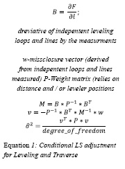
For optimal validation of leveling project, the measurement must be between two sets of known control points or carried out as a loop. Meaning, closure checks can be tested 4 times (between these four known control points). For large areas projects a leveling network is advised, while four tie/check control points are spread evenly at the edges of the project area. Error detection in these case optimally carried out using a conditional LS adjustment. The conditions used for this LS process are the loop closures and closures between the known control points. The errors in this case could be derived directly by the vector of errors (v) from the LS adjustment process, seen in Equation 1.
Control points measured by TS
The regulations and guidelines set the maximal error allowed for a single control point to be measured by TS and the proper way to measure the control point. Nonetheless, guidelines set the maximal and minimal relations between edge size and traverse-internal-angles (left-facing angles) that support these accuracies, thus obtaining certain accuracy rank index (or order). The regulation state, for each ranking index (or order), the appropriate basis control points ranking index and what is the maximal expected miss-closures should be.
While measuring a traverse at the fi eld, minimal Quality Control (QC) is in need. Checking for minimal internal angular miss-closure per site (on every TS post on a control point), and double check for distances between measured control points. These, QC checks and tests help the surveyor measure the traverse as effi ciently as possible.
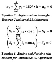
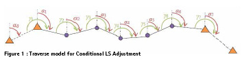
For the conditional LS adjustment, the angular miss-closure (based on azimuth miss-closure) described by Equation 2. The miss-closure of easting and northing values described by Equation 3.
Conditional LS adjustment preformed on the measurement helps greatly in detecting gross errors, and assessing the 2D error ellipses (3D error ellipses) per control point. The traditional conditional LS adjustment is required for both horizontal and 3D traverses, thus the heights calculated from the trigonometric leveling traverse can be adopted ,as close as possible, as a leveled segment in a leveling network.
For basic cadastral uses, traverse based upon two sets of control points measured by GNSS (see chapter: Control Points measured by GNSS). Thus, the two measuring techniques are connected when calculating the error expansion for the control points measured.
Control points measured by GNSS
Control points (2D and 3D control points) derived from GNSS measurements via several methods of measurements:
(1) Post Processing Post processing GNSS data carried out via several techniques:
(i) Base-Rover (single edge vectors only) Note: the base can be one of the following options
(a) "G0 ranking" Permanent GNSS Stations (PGS) network (CORS operated by SOI),
(b) "S0 ranking" Private PGS network (CORS operated by a civil constructor, usually a surveyor),
(c) Known control points as base,
(d) Virtual Reference Station (VRS) (derived by a PGS network, national or private).
(ii) Traverse (based on known control points).
(2) Real Time Kinematic – RTK
(a) Private RTK – rely on a temporal or permanent private base station, which broadcasts corrections for its rover/s,
(b) Network RTK – rely on PGS network, enabling to work with VRS, FKP (regional correction model) and other regional correction models.
Each GNSS measuring type consists with a single known control point measurement per field measurement day.
RTK solution check criteria rely on differences between two set of measurement sessions (180 “fix” epochs per control point, per session) to derive the ranking index (or order) with respect to the short-hand normal distribution function by a sample of two measurements in the population.
Post processing of GNSS data, has more data to handle (rather in RTK which all “processing” done at the field by the GNSS receiver); more data yields more testing criteria – thus has less stability in the solution checking process. The guidelines for measurement process and calculate control points via GNSS instrument describes optimal processing parameters, in order to achieve the most stable solution for the control point position.
Nonetheless, the guidelines register particularly the specific kind of solution needed for horizontal solution and for a vertical solution, depending on the maximal allowed distance from the base station. Once a surveyor measures new points outside the measurement criteria listed by the guidelines (which is carried out by surveyors), the guidelines require the surveyor to apply more time, or a different solution type for the measured vector – such as adding time to the measurement or solving a baseline as Fixed IonoFree solution instead of Fixed solution. The Fixed IonoFree solution is needed for measuring geodetic heights for control points, meaning the surveyor must use a dual-frequency antenna and receiver, which records and handle phases.
Geodetic height measurement, and calculating elevations above mean sea level, is feasible using a unified nationwide undulation model. The Israeli Undulation Model (ILUM) is a geometric height differences model, based on precise GPS benchmarks having (1) adjusted geodetic heights, and (2) precise leveled and loopadjusted elevations. Using ILUM the surveyors can measure geodetic heights and adjust them in a network or traverse fashion, than calculate the appropriate undulation, adding these values yield an orthometric elevation for the measured control points. Nonetheless, unique guidelines for this purpose describe the minimal amount of time per session, and the maximal distance allowed for this measurement and calculation process. Thought needles to mention, the base control point and the tie/check control points, must consist of authorized geodetic height and/or leveled elevation.
The Quality Assessment (QA) process for post processing position solutions require a checklist for several parameters needed to obtain the most stable solution. The checklist is conducted by the values and parameters describes in the appropriate guideline (depends on the solution technique). After the basic checklist entry pass, a reviewer processes the entire job measured by the surveyor. The most general test for a normal statistical distribution, is the final-value test, the distance between the two mean solutions (from the surveyor and the reviewer) must be half the maximal allowed error [3] (per specific accuracy rank index / order) to obtain a certain accuracy rank index (order).
Furthermore, in order to create a standard QA process between the reviewers, readymade project-files (of processing software) with proper preferences (as stated by the guidelines) and spreadsheets tables for comparisons, are commonly used by all reviewers. Prior final position tests carried out, the reviewer tests if the session’s solutions meet the minimal and maximal criteria per accuracy rank index (order), validation carried out by the calculating the distance between the two solutions (per control points).
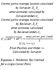
The reviewer’s solution is set to the guideline suggested processing values and a fix control point is set, if needed tempering with the satellites within the solution to ensure a good vector solution. After processing 2 sessions, and assuming all vectors have satisfactory error estimates, least square adjustment and calculating point position is carried out. Upon these solutions, the reviewer tests and sets the accuracy rank index (or order) for each point, by checking the geometric distance (horizontal and vertical, apart) between the solutions as can be seen in Equation 4.
Although the single edge post processing solution, as describes before, is a wellpreferred fieldwork project type by most surveyors, the reviewers most certainly prefer the traverse project type. The traverse project type takes much more resources and relies on more than one GNSS receiver (and antenna). A vector network that uses two known control points as the base and the control. Using this method of surveying a full miss-closure report is created and it is much easier to detect error of measurement or processing. The LS process resembles the TS measurement, thus can be crosscheck using TS instrument (if line of sight is available).
An important tool for internal validation of a GNSS measurement project, crucial for GNSS vector networks and GNSS traverses is the Loop closure. Validation using loop closures test if the vector processing calculated variance-covariance matches the internal geometry created by all vectors closing a loop (or creating a flow between two known control points). In the QA process, all error-estimations and positions of the control points calculated by both reviewer and surveyor should agree on same accuracy rank index (order). If this is not the case, the surveyor is addressed to accommodate this issue and a lower ranking index (or order) is acceptable or more measurement sessions are in order. If the reviewer is not certain that the solution is as stable as it should be, field surveyors from SOI can be sent to the field to validate some of the internal relations between the calculated control points – such as measuring the distance between sets of control points using TS instrument. The measured distance must be within the maximal error of the two control points measured, or will derive the accuracy rank index (or order) for these control points respectively.
Private GNSS permanent network authorization
Currently, authorization of private PGS network is subjected to comprehensive validations at SOI, and is regulated under unique guidelines for establishing, maintaining and operating a private PGS network.
The validation of such network concludes: (1) visit to each station location for monument structure stability (preferably a monument to match the IGS guidelines for CORS monuments [4]); (2) three long static (24 hours) sessions; (3) LS adjustment with specific maximal accuracy (CEP at 95% confidence, 1cm horizontal and 2cm vertical). Each session must rely on all “G0 ranking” national PGS network (first order); with a full 3D fix on all their positions.
The post-processing of each session must consist with: (1) precise GNSS satellites orbits, (2) low data interval frequency processing (for lowering the noise in the vector processing solution) and, (3) sufficient elevation mask – usually preferred 15 degrees, lowering down to 12 degrees (same elevation mask is needed for all sessions).
The hardware used for receivers and antennas at each site must be with geodetic features, and must be reinforced to its physical base (rock, boulder, building etc.). Furthermore, tests carried out for signal to noise ratios (SNR) and Multipath using TEQC (UNAVCOs free RINEX utility). If values of these parameters exceed standard maxima, the position-adjusted errors will determine rather the site will be authorized or not (the L-band spectrum in Israel has relatively high noise due to high density of operating transmitting object, such as RADARs and microwave communication towers).
The reviewer, as in other projects, recalculates the sessions and preform network adjustment. Differences between the session’s adjusted networks tested for maximal horizontal and vertical error per control point for validation. Finally, the separation between the two mean positions of the calculated, the distance must meet half the criteria listed in the specific guidelines [3].
Communication between the surveyor and Survey of Israel
TOPOCAD, a web based service to help the surveyors and the reviewers communicate, the service allows the surveyor handle his projects with respect to the regulations and accuracies demanded. TOPOCAD handles the full history of applicable forms sent by the surveyor and authorizations granted by SOI reviewers. TOPOCAD creates an ordered working methodology, and helps the surveyor track the entire authorization needed for a specific type of project (cadastral, engineering etc.). TOPOCAD enables some cooperative relations between the surveyors, and any connected surveyors profiles; thus letting the collaborators, view partial or full information about each other’s project.
Logging to TOPOCAD requires the surveyor have an active license and a chip for identification via card reader – meaning the connection is personal and is in the full reliability of the surveyor. TOPOCAD is part of sets of government websites, thus, assimilated in a government secured site.
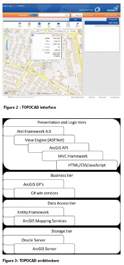
Recent update from the Surveyor-General, parts of the entire geodetic database is fully free for surveyors and is accessible via TOPOCAD for the surveyors to use for planning, calculating and usage in their projects.Currently, TOPOCAD contains some useful applications, and the vision is to let the surveyors numerous tools to validate his work prior sending it for reviewing at SOI. In addition, reviewer would use fewer resources on default initial validations (required by the regulations) and more resources for geodetic, statistic and geometric validation tests. TOPOCAD encapsulates numerous data and information for the surveyors and enables quick access to it, as can be seen at Figure 2.
Technological aspects
The Database (DB) implemented for TOPOCAD is a Relationship DB Managements System (RDBMS) by Oracle. The entire site and its services were coded in the following languages: (1) HTML, (2) JavaScript, (3) CSS, (4) ASP.Net, (5) C# (6) SQL and (7) PHP.
Geographic Engine for display and Geo- Processing (GP) is ArcGis from ESRI ltd. The Geographic and Geodetic DB is displayed using the ArcGis Server technology implemented by ESRI.
The ESRI geo-processing engine, implemented in the ArcGis server, enables a large set of geo-analyses and geo-statistics tools, in addition a large amount of algorithms such as “re-projection on the fly”.
The TOPOCAD search engine is based on “Elastic Search” technology, meaning search will work faster and will perform its search logic of a big data search engine. The search engine have two modes: (1) free search and (2) modular search (search refined by the user). “Elastic Search” technology is capable of searching alphanumeric and geo data as well. The search engine is updated and re-indexed once a day for optimal resources usage.
TOPOCAD architecture
TOPOCAD architecture as described at Figure 3, divided to 4 tiers: (1) presentation and logic tiers, (2) Business tier, (3) Data Access tier and (4) Storage tier.
The storage tier consist of two data structures: (1) metadata and alphanumeric data, and (2) geospatial data. In addition, the storage tier contains two databases: (1) Data database and (2) Management database. The Business tier containing win-services for high resources and heavy GP algorithms, these processes run on a different physical machine. These processes partially described in the following section.
Services for surveyors
Though currently TOPOCAD includes several services that are available for surveyors as tools for their work, such as (1) approximate coordinates convertor (between Israel’s national grids, past and current), and (2) a cadastral transformation calculator.
The Approximate Coordinate Convertor applies several computational algorithms for transforming and re-projecting coordinates between Israeli grids (former and current). The Cassini-Soldner grid (established and measured by the British mandate at the 1920s) was not a complete grid for the nation; it spread mainly at civil population concentration. The former Survey regulation let the surveyors build local grids for surveying, thus creating a great variant of accuracies. Thus, the transformation between this grid and any other must rely on parcel-border controlpoints and not only on base control points.
The irregularity of carrying out a transformation between these grids leveraged SOI to build a process and guidelines for surveyors on how to calculate the transformation parameters properly (mainly translation) between the grids, when the Cassini-Soldner is in use. In-order to contribute to the process of maintaining sufficient accuracy while preforming transformation for cadastral usage and embedded a calculator at TOPOCAD sites for the surveyors. The cadastral calculator uses two sets of homological points (a set for each grid) and calculates the transformation for two optional types: (1) translation, and (2) conformal (translation, rotation and singlescale). The transformation calculation process uses a LS adjustment for the transformation parameters estimation.
The cadastral calculator takes into account the accuracy ranking index (or level) of the points as internal weights for the LS adjustment. Furthermore, the LS adjustment weighting process based upon hat matrix, which enable quick detection of errors. The weighting matrix is combined from three different weighting technics (1) accuracy based weighting, (2) distance separation from centroid, and (3) hat matrix. Weighting estimates standard deviation between the two homological points [5], thus creating the correlation between the distribution of the points in the sample. The weight functions for each point described at Equation 5and Equation 6, and the weighting matrix built as a block diagonal matrix.
Accuracy weighting matrix for each homological point set is (a value for each position ordinate):
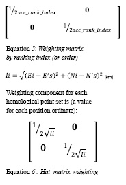
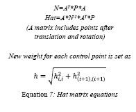
The complete weighting matrix is a product of all three weighting functions and fulfills the internal ration of a control point (with its homological control point) in the set. Hat matrix as a weighting component for the full weighting matrix is built as described at Equation 7 [6].
Initial weighting matrix P=I
calculating partial differentiate parameter matrix A (via translation and rotation model)
Future work
TOPOCAD is an internal product of SOI (R&D division), therefore always under development for more usages. Numerous add-ons for the future versions are: (1) geo-processing engine and services, (2) Big data search engine, (3) cloud server and site infrastructure to match it, and (4) mobile first viewer for maximal screen compatibility.
Services for geodetic measurement solutions will be combined as webservices for the surveyors. These services will validate the measurement minimal requirements addressed by the regulations and guidelines, and will produce a solution for the measurements taken. The services will mainly address measurements taken by TS and leveler (traverse calculations, geometric and trigonometric leveling as well), a site for processing GNSS RINex (Receiver Independent Exchange format) data exists under the main servers of the CORS.
The Big data search engine based on the freeware software and code of ElasticSearch, capable of solving a growing number of use cases. The ElasticSearch engine has numerous advantages, such as, capable of fast working on a big and various data stored in a large storage, updates indexing every morning.
Algorithm improvement for the geoprocessing and services are planned for optimal response time, and minimal processing time. Furthermore, information (including calculations results and survey areas) will be shared between the surveyors for maximal coverage and minimal misfit to take place between different surveyors working at same location.
Future version of TOPOCAD will contain a lean management module for detailed geodetic processes, and will have open and free access to all this information, for all surveyors. Furthermore, TOPOCAD will prepare numerous Business Intelligence (BI) reports about the entire working and communication process between surveyors and SOI reviewers.
Conclusions and discussion
Regulations and guidelines set the minimal required field measurement and processing parameters values in order to achieve the needed accuracyclass (or order) for a new control points. Partials of the requirements assist the reviewer to filter and check the measurements taken by the surveyor. Reviewers handle each job in an unbiased fashion and inspect them in a different environment used by the surveyor, hens the random errors of the measurement are being tested and biaserrors and gross-errors are easy to test.
Each project reviewed is solved and crosschecked using a different set of processing programs to keep a maximal level of independency between the surveyors and the reviewer solutions. Afterwards, the solutions are tested by normal-random error distribution shorthand formulas.
In order to accommodate regularized and valid form of communication and accuracy tests, surveyors getting access to online tools and services for testing measurement accuracies and validating their jobs.
TOPOCAD, as a communication platform, will let the surveyor submit the job, only if several properties are marked as passed – such as accuracy ranking, valid check-up control point position etc.
As a future effort, services of field measurement geo-processing, such as TS and leveling, will be accessible to surveyors for processing, or doublechecking their results. A web service for post processing GNSS measurements is available via the APN CORS site.
References
[1] V. FISHBEIN, Y. FELUS, S. BARAZANI and R. REGEV, “The New Israeli Survey Regulations,” p. 14, 29 May 2017.
[2] STEINBERG, Gershon; EVENTZUR, Gilad;, “Permanent GNSS Networks and Official Geoid Undulations Model as a Substitute for Orthometric Control,” p. 11, 8-13 10 2006.
[3] M. R. SPIEGEL and L. J. STEPHENS, “Theory and Problems of Statisics Fourth Edition,” Shaum’s Outlines Series, pp. 95-123, 01 01 2008.
[4] N. G. S. National Ocean Survey, NOAA, “Guidelines for New and Existing Continuously Operating Reference Stations (CORS),” 01 01 2013.
[5] A. A. Nielsen, “Least Squares Adjustment: Linear and Nonlinear Weighted Regression Analysis,” 19 09 2013.
[6] D. C. Hoaglin and R. E. Welsch, “The Hat Matrix in Regression and ANOVA,” vol. 32, no. 1, pp. 17-22, 18 01 2012.s


 (2 votes, average: 3.00 out of 5)


Leave your response!