| Positioning | |
Assisting visually impaired using smart-phone sensors
A project at the University of Nottingham, is working to investigate indoor positioning and object recognition to aid the blind. As part of that project, tests were conducted to assess the quality of the various sensors of a smart-phone, the aim was to assess whether the smart-phone could be used as the sensor platform to enable the development of assistive technology for the visually-impaired |
|
 |
|
The ability to navigate in an outdoor or indoor environment and recognise objects is one which is taken for granted by sighted people. However for the visually impaired this task is less ‘trivial’. Spatial orientation depends on coordinating one’s actions relative to the surroundings and the desired destination. It refers to the ability to establish and maintain an awareness of one’s position in space relative to landmarks in the surrounding environment and relative to a particular destination (Ross and Blasch, 2000). Maintaining spatial orientation is a significant challenge for individuals with visual impairment. Way- finding or navigation is the means by which a person utilises their spatial orientation in order to move through the dynamic surroundings and arrive successfully at their destination. This successful navigation requires continuous feedback from the environment. A major part of this feedback information are cues used to monitor “environmental flow”. According to Ross and Blasch (2000), “Environmental flow refers to the ordered changes in a pedestrian’s distances and directions to things in the surroundings that occur while walking” (pp. 193). Therefore, maintaining orientation is largely about keeping track of this environmental flow. The environmental flow of walking can be perceived through various senses such as sight, hearing, smell, and the ability to detect heat.
For the blind and partially sighted the visual cues which are a significant part of monitoring the environmental flow are either severely limited or non-existent. Thus the challenge is to be able to use man-made sensors and technology such as the smart phone based sensors to assist such individuals in monitoring the environment and collecting cues/ data about the environmental flow.

Tests were conducted to assess the quality of the various sensors on the phone that can be used to aid positioning and object recognition. The aim of the tests was to assess the quality of the following sensors on a mobile phone: GPS, Accelerometer, Gyroscope, Compass and Camera.
Several tests were conducted using various smart phones. For the GPS, accelerometer, gyro and compass tests the iPhone 4 was used. For the camera tests the iPhone, HTC Wildfire and a Nokia 6500-Slide were used. These were considered as being representative of mid to high end off-the-shelf smart phones currently available. An iPhone Application was written to record data from the GPS receiver, tri-axal accelerometer, tri-axial gyro and digital compass present on the iPhone.
GPS, compass, accelerometer and gyro tests
Tests were conducted to assess the accuracy and precision of the GPS receiver in the smart phone tested. Both static and moving tests were conducted. While the GPS receiver is mainly aimed at outdoor positioning, the ability to navigate seamlessly between outdoor and indoor environments using a single device is important to users. Therefore an assessment of the GPS position quality is required. The GPS data rate was at 1Hz while the accelerometer and gyro data collection rate was at approximately 10Hz.
Test 1: Static GPS
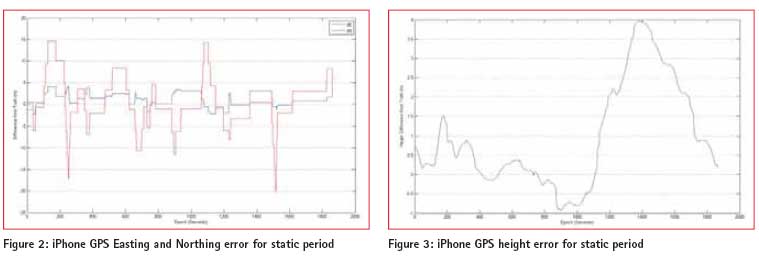
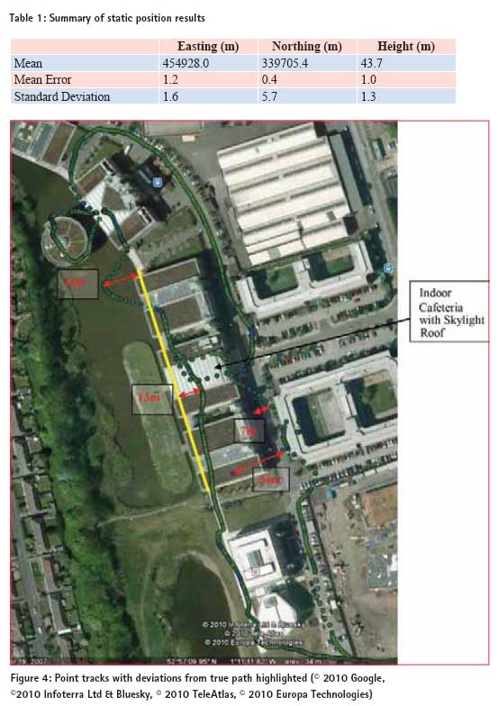
The phone was placed for a static period on a pillar on the roof of the Nottingham Geospatial Building (NGB) whose coordinates are known. The measured coordinates from the iPhone for a ~30minutes period, was compared with the known coordinates of the pillar. The latitude, longitude and ellipsoidal height results recorded from the phone was converted into Ordnance Survey (OSGB36_02) Eastings, Northings and Height using Grid InquestTM. The iPhone position error in the east, north and height components are shown in Figures 1 – 3. For the ~30 minutes static period, the statistics summarises the results as mentioned in table 1. The results in the heights appear to be better than the plan which is contrary to expectation. This may be to due to the effect of multipath or alternatively some internal filtering of the height data.
Test 2: Kinematic GPS Tests
– Outdoors and Indoors This test was aimed at assessing the quality of the smart phone GPS receiver in a variety of environments. This ranged from open outdoor, to partially obscured, to indoors (with skylight roof). The smart phone was held in the palm of the hand in front of the walking user.
Route: walking from the Nottingham Geospatial Building (NGB) ->along Triumph road ->along a straight path ->turn about 100 degrees ->and then along a covered pathway, ->around the Library (partially obscured area) ->then along the open pavement close to buildings ->inside the cafeteria (indoors but with skylight type roof structure) ->back to NGB.
Figure 4 shows a view of the route around the buildings with the deviations from the true path travelled highlighted.
The yellow line shows the covered pathway. The size of the deviation from the desired path at certain locations is highlighted in red. In the covered path the deviation increases up to about 13m in the middle and about 24m at the end. Good to medium quality position solutions are available in the indoor cafeteria area as lock to the satellites was maintained. This is due to the type of roof structure which is either glass or some form of clear plastic. Along the footpath between two buildings the position deviates by about up to 34m at a point. This is because of poor satellite visibility due to obscuring by the buildings.
Test 3.1 – Compass Test (Outdoor)
The aim of this test was to assess the quality of the inbuilt compass in the smart phone tested in the context of an outdoor environment.
This test was carried out on the Jubilee campus, walking in a straight line and then making a turn and walking in a straight line for about 70 metres then stopping. The compass measurements were extracted from the iPhone and are shown in Figure 5. There are likely to be small errors due to there being some misalignment between how the phone was held during the test and the direction of travel.
‘True’ values for the two heading directions travelled were taken from Google Earth. These are 277º and then 341º.
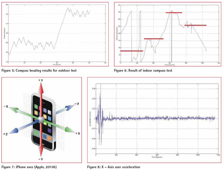
In Figure 5 above the change in direction can be seen in the compass readings. The compass readings for each direction fluctuated around a mean value.
Mean1 = 276º and Std.Dev1 = 7º
Mean2 = 345º and Std.Dev2 = 5º
For a 5º heading error, after 1 m (assuming no other errors) the deviation from the desired end point would be 0.09 m while after 10 m it would be 0.87 m. For a 10º heading error after 10 m the deviation will be 1.74 m. Therefore in the outdoor context tested, the smart phone compass provided good orientation information which could be used in assisting navigation for the blind and partially sighted.
Test 3.2 – Indoor compass test
This test involved walking in the open plan office area of the B floor in the Nottingham Geospatial Building (NGB). Firstly walking parallel to the wall from front to back, (walking past some metal cabinets). Then turning 90º and walking in a straight line parallel to the back wall, turning around 180º, then returning back, turning 90º and heading back to the starting point.
Using the coordinates of the high precision GPS receivers on the NGB roof to determine the building heading, the general heading values for the manoeuvre conducted should be 79º ->169º ->349º ->259º. This has been approximately indicated by the red overlay on the graph in Figure 6 (NB: the transition time for the red line is approximate).
The metal cabinets were a source of error for the digital compass in the iPhone which is a magnetometer (The GPS receiver is then used internally to compute the difference between true north and magnetic north). During the tests while walking past one of the metal cabinets a message regarding disruption error to the compass was flashed. It can be seen in the results that the indoor environment is quite challenging for the digital compass due to the close proximity of metal objects. Thus leading to errors of up to 100º in the compass heading as can be seen in Figure 6. Calibrating the compass for each new environment may improve the results but would be impractical to expect to user to calibrate for every indoor environment or room.
Test 4 – Noise resolution of accelerometer and gyro
This test was a static test where the iPhone was placed stationary and undisturbed on top of a desk in the office. The user acceleration in the x, y and z directions was recorded, as well as the attitude and compass heading. The iPhone axes are shown in Figure 7.
Acceleration:
The iPhone application recorded both the acceleration (with gravity) values and the user acceleration where the gravity component has been removed. The user acceleration result in the X, Y, and Z axes are shown in Figures 8 to 10 respectively.
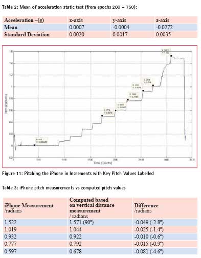
The acceleration spike at the beginning of Figures 8 – 10 was due to the placing down of the phone onto the table after data recording had been initialised. After that the acceleration values were close to 0g for all axis. Although the z-axis had a larger offset from the 0g value (Table 2).
Attitude Test – Pitching (Turning about the iPhone’s X-axis)
The phone was rotated about the x-axis in small increments every 10-20 seconds. The user attitude information from the iPhone was extracted and is shown in Figure 11. The gyro actually measures angular velocity. The pitch and roll values are computed from the accelerometer values which is then smoothed by the gyro data.
The phone was pitched up in gradual increments up to 90 degrees (standing on edge). This can be seen clearly. Some measurements were taken of the horizontal projection of the phone during this procedure. This was used along with the length dimension to get an independent approximation of the pitch values. The comparison of the results are shown in Table 3.
The above attitude tests show an orientation error of up to about 5º in the pitch. These results show that the smart phone accelerometer and gyro have better stability than the compass and thus for indoor environments the accelerometer and gyro can be used to provide relative orientation information to the blind or partially sighted user.
Comparison to other low cost IMU specifi cations
The foot-tracker developed by Hide et al. (2009) utilises MicroStrain 3DM series (3DM-GX1 or 3DM-GX3-25) inertia sensors. The MicroStrain 3DM-GX1® and 3DM-GX3® -25 are high-performance, low-cost miniature Attitude Heading Reference System (AHRS), utilizing MEMS sensor technology. It combines a triaxial accelerometer, triaxial gyro, triaxial magnetometer, temperature sensors, and an on-board processor running a sophisticated sensor fusion algorithm to provide static and dynamic orientation, and inertial measurements (Microstrain, 2011), (CMU, 2010). It has an orientation accuracy of: ± 0.5° typical for static test conditions ± 2.0° typical for dynamic (cyclic) test conditions & for arbitrary orientation angles.
And an accelerometer bias stability of:
± 0.005 g for ± 5 g range
± 0.003 g for ± 2 g range
Its other bias specifications can be found in (Microstrain, 2011). The accelerometer and gyro on the iPhone are a lower quality of inertia sensors than the MicroStrain 3DM range.
Camera – Object detection tests
 Tests were conducted to assess the quality of the images produced by various types of smart phones and the ability to extract feature information from such camera photo images. Matlab was used for the image analysis. Three phones were used in the image analysis tests, the HTC Wildfire, the iPhone 4 and the Nokia 6500 slide. The following are their camera specifications:
HTC Wildfi re:– 5 megapixel colour camera with LED flash (HTC, 2010). iPhone 4: – 5 megapixel still camera with LED flash, VGAquality photos (Apple, 2010a).
Nokia 6500 slide: – a 3.2 megapixel camera with Carl Zeiss optics, auto focus, and 8x digital zoom. Has a powerful double LED flash (Nokia, 2010).
Simple Shape ID – Circle Identifi cation:
The following was used as a metric to identify round objects in an image: Metric = (4 x pi x area) / perimeter2.
This metric is equal to one only for a circle and it is less than one for any other shape. The discrimination process can be controlled by setting an appropriate threshold. Different shapes were cut out from white paper and placed on a black background. These were photographed using the selected smart phones. The photographs were taken in an indoor environment with indoor lighting on, hence the presence of shadows as can be seen in Figure 13. Photos were taken using the three phones one after the other at the same time of day and under the same lighting conditions. The position it was taken from was approximately the same. The images were converted to binary and noise in the data was cleaned off before analysis.
HTC Wildfire
The various shapes in Figure 12 have been highlighted in different colours and their boundaries traced. It can be seen that the circular shapes have a higher metric of 0.83 and 0.85 respectively. The fact that the shapes were hand cut out, as well as the clarity of the image are likely to be the contributors to why the metric is < 1 for the circular shapes. In this image a threshold of about 0.78 can be applied to discriminate between the circular and not circular objects in the image. This indicates that a smart phone image can be used for shape identification.
iPhone 4
The iPhone photo was more impacted by the shadow on the image. This resulted in the rectangular shape which was in the shadow area being removed when the image was converted from colour to grayscale and then binary. Thus the circle identification was not effective as the large circle was distorted leading to a low index value of 0.42. The smaller circle was clearly outlined with an index value of 0.70 (lower than that from the HTC). It is possible to perform some further pre-processing or to use a different grayscale threshold to reduce the shadow effect for the iPhone image. However for this comparison test it was desired that the same script be run for all the photos for proper comparison.
Nokia 6500 Slide
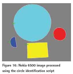 The original Nokia image compared to the others initially appeared to be a lesser quality than the others. However the shape identification routine performed well with it. The large circle had a metric of 0.82 while the smaller circle had a metric of 0.78 (Figure 16). The tests show that it is possible to identify shapes based on images taken from a smart phone camera. This can then be used as part of an object identification routine such as detecting the shape of a Fire Exit or the symbol of a toilet sign. In the test conducted the HTC Wildfire 5 mega pixel camera showed the best results. The iPhone camera also of 5 megapixel showed poor results due to the impact of the shadow. While the Nokia 6500 although only 3.2 mega pixels gave good results. The type of flash used may be a contributing factor as the Nokia 6500 has as dual LED flash. Further tests to investigate the impact of camera orientation and lens distortion on shape detection is also required.
Conclusion
Currently available off-the-shelf mid to high-end smart phones are today equipped with a range of sensors such as GPS receivers, cameras, accelerometers and gyros. These sensors were introduced to enable activities such as the changing of view from portrait to landscape when the phone is tilted, image stabilization, and outdoor position guidance. This has further evolved into the playing of games and other such applications. These sensors are low cost, low grade sensors which were not designed for high accuracy or high reliability applications. The tests conducted showed that the Compass on the phone tested was able to provide fairly stable results outdoors however, in the indoor environment tested it proved unreliable due to the influence of metal objects in the indoor area. Nevertheless, the tests conducted showed that if this data is integrated with gyro data it can provide useful orientation information. The iPhone GPS receiver had an accuracy of a few metres and was able to provide positions in an indoor environment with a clear roof structure. However after navigating underneath the covered walkway (Figure 4), the position solution drifted by up to 24 metres. Integration with the onboard inertia sensors would assist in correcting such errors. Further research has been done in this project utilising the smart phone inertia sensors to detect the walking dynamics of the user and based on this, computing the distance travelled.
The camera tests conducted have shown that object identification can be conducted on the images from the various phones including the 3.2 Megapixel Nokia 6500 camera. However, it could also been seen that effects such as shadows in the image could adversely affect the object recognition capability. The camera can be utilised in detecting objects/symbols such as Fire exit or wet floor signs (Bail, 2009), or can also be incorporated in the navigation algorithm (Kessler et al., 2010).
The tests results in this paper have shown that the smart phone sensors while having some limitations, if integrated effectively can provide useful information on the environmental flow of the user and thus aid in positioning and navigation within an indoor context. Further tests conducted as part of this research have also shown that the smart phone sensors can be used to provide context awareness (Collins, 2010) information as well as a measure of orientation and distance travelled by the user. This is an area of ongoing research at the Nottingham Geospatial Institute – University of Nottingham.
Acknowledgements
This research project was funded by Caecus Ltd a social enterprise developing technology for the blind and partially sighted. The data collection iPhone application was written by my colleague Gary Wang at the GNSS Research and Applications Centre of Excellence (GRACE), University of Nottingham.
References
1. http://www.apple.com/iphone/specs. html (Last Accessed December 2010)
2. http://developer.apple.com/library/ ios/#referencelibrary/GettingStarted/ Creating_an_iPhone_App/index.html (Last Accessed December 2010)
3. http://www.htc.com/www/product/ wildfire/specification.html (Last Accessed December 2010)
4. http://kitchen.cs.cmu.edu/ Home/3DM-GX1-Datasheet-Rev-1. pdf (Last Accessed December 2010)
5. http://files.microstrain.com/ product_datasheets/3DM-GX3-25_ datasheet_version_1.07a.pdf (Last Access November 2011)
6. http://www.nokia.co.uk/find-products/ all-phones/nokia-6500-slide/specifications (Last Accessed December 2010)
7. Bail, S., (2009), Image Processing on a Mobile Platform. MSc Thesis, University of Manchester, Faculty of Engineering and Physical Sciences.
8. Collins, J, (2010) Context Aware Navigation Algorithms. Published online in GPS World Tech Talk Blog August 13th, 2010. http://techtalk.sidt. gpsworld.com/?p=645#more-645
9. Hide, C., Botterill, T., and Andreotti, M. (2009) An Integrated IMU, GNSS and Image Recognition Sensor for Pedestrian Navigation. Proceedings of the Institute of Navigation (ION) GNSS Conference 2009.
10. Kessler, C., Ascher, C., Frietsch, N., Weinmann, M., and Trommer, G. F. (2010) Vision-Based Attitude Estimation for Indoor Navigation using Vanishing Points and Lines Proceeding of ION/IEEE PLANS, Palm Springs, USA, May 2010, pp 310 – 318.
11. Ross D. A., and Blasch, B. B. (2000). Wearable Interfaces for Orientation and Wayfinding. In Proceedings of ASSETS’00, November 13 – 15, 2000, Arlington, Virginia. ACM 1-58113-314-8/00/0011.
My Coordinates |
EDITORIAL |
Conference |
Let’s click GIS into gear! Data is the fuel |
No Coordinates |
Hunting Treasure |
Mark your calendar |
June 2012 TO February 2013 |
News |
INDUSTRY | LBS | GNSS | GIS | IMAGING | GALILEO UPDATE |





 (10 votes, average: 2.50 out of 5)



Leave your response!