| Mapping | |
UAV system with terrestrial geo-referencing for small area mapping
This paper describes the first stage of our research to develop small land parcels mapping distributed evenly by combining an Unmanned Vehicle Aerial Mapping using UAV and terrestrial method, where the terrestrial method is used to geo-reference photograph directly |
 |
|
 |
|
|
 |
|
UAVs in this study is a system which is divided into two sub-systems that are attached to the vehicle itself consisting of a camera, navigation instruments, etc. The second sub-system is a system on land that is composed of digital terrestrial measuring devices. To support the implementation of the study, one should design an instrument/ vehicle appropriate to the research requirement. Thus, it allows modification in the design of an instrument in accordance with the required specifications.
In the mapping technology, the UAV has provided several options to meet the need for the provision of data, especially the data on parcels. Tendency to derive data from all environmental conditions in ‘economical’, ‘up to date’, manner and accuracy that meets the mapping standards is the base of this research. This tendency can be used for accurate, complete observation and control over of land ownership status or plots in rural areas and small parcels in the area that lie scattered. Development of UAV technology design aims to make the technology more adaptive with low cost and use of the instrument as a carrier vehicle for the camera in aerial photography by combining traditional photogrammetric technology. So far, the massive land parcels mapping are common with high-resolution satellite imagery (Quickbird, Geoeye, World View) and in certain areas, aerial photography is utilized. But the method is constrained by the high price of the image (if it is related to the size of the area mapped). The time for ordering images is constrained by several factors – one of the most common obstacles is cloud cover conditions, followed by regulations on the purchase of the image. The UAV capabilities in overcoming deficiencies of imaging using the satellite imagery are an excess of UAV technology in mapping parcels. However, the main disadvantage in the use of UAVs is lying in the resultant geometric precision of photograph/image, as it is associated with unstable camera carrying vehicle/aircraft. Modification of existing method will be carried out to solve these problems, which is an objective in this research generally.
Background
The rapid growth of population led to the requirement for land for developing more residences or parcels, resulting in the change in data on land use, both spatial and attribute, in the land administrative system. The phenomenon suggests the importance of the information on dynamic land ownership along with changes in the population in relation to treatment of land/parcels. Relationship with these changes spawned the need for a system that can record data in an accurate manner in defining land status. Such changes lead to transformations of land spatial and textual database, including data on control, ownership, use, and land utilization. To address these problems, one of the measures is to take fast, modern, systematic and complete construction of base map and thematic map covering basic geographic element data, facility/important places and governance possession, use and utilization of land on a large scale.
In his research, Cunningham, K. (2011) found that the quality of the cadastral survey is directly related to population density and variety for each village, so often found in some of the villages with no cadastral maps that meet the standards of cadastral maps. The existence of the cadastral map for each village with diverse characteristics of population and topography is a challenge to seek a method in the provision of cadastral maps in every village in the region of NKRI. Another problem is the challenge to be able to map the parcels accurately in a small area, and between the parcel and the others is not adjacent/distant/ within a single stretch of one another.
The main problem in spatial land database updating is the availability of a map with a resolution and accuracy that meets the specifications of land maps. Regulation of the State Minister of Agrarian Affairs/Head of National Land Agency Number 3/1997 on the Implementation of the Provisions of Government Regulation No. 24/1997 on Land Registration in Article 13 stipulates that the basic map of registration is made on scale 1:1,000 or greater for residential areas, 1:2.500 or greater for agricultural areas and 1:10.000 for large plantation areas. Thus, the necessary imagery with a resolution greater than 0.5 meters for residential areas, for agriculture is greater than 1.25 meters and 5 meters for plantations, or it can be concluded that to map the parcels that have high-resolution imagery.
To obtain high-resolution images that are costly (if it is related to the mapped area of parcels), the time for procurement is over 2 months (if not more) and are often constrained by cloud cover. So the approach of photogrammetry (using manned aircraft) can be an option, but expensive aircraft lease and the requirements to fly a plane as a vehicle carrying the camera is an economically ineffective method, especially when the area coverage will be mapped is small (<1,000 ha) and when the parcels being mapped lie scattered far apart from one another.
Another problem commonly encountered with regard to the topographic characteristics is that in several regions of Indonesia there are distinctive challenges in terms of both topographic mapping accessibility and implementation of mapping. The mapping by terrestrial or direct observation in the field has been recognized for precision that meets the technical mapping specifications. However, constraints of accessibility, weather and the extent of the area surveyed by such methods are rarely used in areas with characteristics of undulated topography and difficult accessibility. These situations led us to modify some surveying techniques to meet the necessity of land parcels map.
Objective
Based on the description in the background section, the objective of this research is ‘Improving Land Parcels Mapping Method by Integrating UAV System with Terrestrial Direct Georeference System’.
To achieve the objective, innovative methods were used to provide spatial data by combining the low cost photogrammetric method using Unmanned Aerial Vehicle (UAV), with a terrestrial method that has high accuracy as control point on the ground. Given the research, innovation will result in the method of mapping parcels with the following advantages:
1. Can be used on topography with high risk and hard accessibility.
2. Can be used to map small parcels and some scattered parcels located far apart from each other.
3. Have high temporal and spatial accuracy.
4. At low cost.
Methodology
In general, the availability of an aerial photo map for the purpose of making a land parcels map in Indonesia is still far from completion. Satellite imagery is often used to identify parcels boundary with level of resolution, and the accuracy is not as it is expected. In addition to not meeting the resolution for the creation of land maps, the parcels to be mapped often are found in areas that are difficult to map even by remote sensing methods as a result of cloud cover or the degree of openness of the land which makes it difficult to be mapped directly in the field. Photogrammetric methods in either large, medium or small formats are generally plagued with problems of availability of aircraft, licensing in photography, dense cloud cover that requires the aircraft to fly quite low, cost in photography, etc. Thus for small acreage, this method assessed is not effective. We therefore need a method to map parcels that can overcome these problems, and one of the methods that will be used in this research is the method of unmanned aerial mapping, also known as Unmanned Aerial Vehicle (UAV).
UAV Vehicle Design
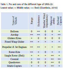
There are several unmanned vehicle designs to be considered in the mapping of plots, as shown in Table 1. At the beginning of this study, we plan to use fixed-wing aircraft. However, after the examination of the signal response capability on the total station instrument was complete, we then used quadrotors.
We planned to use fixed wing gliders UAV with consideration to overcome the problems of payload capacity limitation and wind factor, that are becoming a major problem in maintaining vehicle stability when aerial photographs are taken, as shown in Table 1. However, to find out more definitely the type of aircraft that is appropriate to this research, we first conducted a study of aircraft designs to determine which vehicle type was adaptable with the total station (TS) instrument capabilities that will be used to determine the position of the camera. This study used non-reflector total station’s top con GPT 3500 and GPT 7500.

To understand the tracking rate of total station instrument in determining moving objects, we make a simulation measurement with moving cars with different speeds as the targets. In order to obtain position data/ coordinates of target of various speed, we carried observation around the freeway which allow cars to move with speed until 100 km/hr. From the observation, we found that for a car with speed of about 40 km/ hr with a distance of 112 meters to the car, TS need 11 seconds to process the signal; meanwhile for cars at faster speeds, a longer processing time is necessary. The most suitable vehicle for this research is the vehicle with the ability to fly at speeds below 40 km/h and yet be stable. This specification cannot be achieved using fixedwing aircraft/fixed wing. As a solution, we have to consider an alternate design and UAV of quadrator type equipped with navigation system and auto pilot. To design this type of aircraft, the team collaborates with PT. Terrascan. There were three quadrotor designs prepared in this study: type X650, X450 and type Q800.
The vehicle should be designed in such a way that makes it able to support time synchronization process between the time for photo capturing by onboard camera with the distance and direction angle measurement time by total station on the ground. Three options offered in order time synchronization:
1. Set the time/timer on camera for the initial photo taken and interval of photo taken.
2. Equipe UAV with LED lights system that will flash on when the camera take the picture.
3. The aircraft can support the aerial photography in ‘Stop and Go’.
The third option cannot be realized by fixed wing UAV. The main advantage of quadrotor design makes it possible to fly and take photos at very slow speeds <40 km/hour, even stop over an area of interest as required or photograph when motionless and continue flying, in contrast with fixed winged aircraft. Nevertheless, beside those advantages, quadrotor type has some major drawbacks in payload and endurance, specially in battery capacity. For this case, we have to be more careful in monitoring the battery capacity and load. In this study, we use Lippo 2200 mAh 3 cellular battery with the respective lifetime of 5 minutes each.
The quadrotor type X650 body design consists of a metal frame the makes it more easy to reflect waves emitted by a total station, making it faster to get the vehicle position than type X450 whose vehicle body is made of melamine. Having a melamine material body, longer time is necessary to get the vehicle position data when type X450 is used. But in terms of flight stability, X450 is more stable than X650. UAV operator can maintain X450 position in a point for some minutes to help surveyor on the ground track it easily and take its coordinates. For those reasons, we redesigned aircraft type X450 body with aluminum foil coated to reflect total stations wave better in the next research.
Measurement of Photograph
Position In general, the methodology to be used in this study is illustrated in Figure 3.
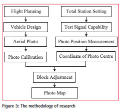
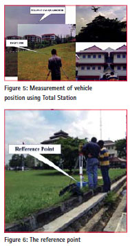
The measurement begins with study on vehicle construction design to be used for photography and the digital camera used is a regular digital pocket camera, such as canon 100s onboard in vehicle body. The UAV is also equiped with GPS navigation to monitor UAV system status and its position during flight, specially to direct the vehicle to some interest target/ land parcel. Camera position was measured using a non-reflector total station instrument GPT 7500 or GPT 3500, installed just above the ground control points of known coordinates as reference, so that by knowing the distance and angle to the camera, the camera’s coordinates can be determined using polar coordinate and trigonometric system.
Basically, the land parcel photography using UAV is photogrammetric method where the photography is carried out using digital camera attached to the vehicle, but the vehicle used is a small unmanned aircraft managed by a remote control. The relationship between the aircraft and the total station is depicted in figure 4. The combination of polar and trigonometric method in photo coordinates determination are the key in this method.

As illustrated in figure 4, a is the measured horizontal angle of UAV/ camera from back sight point. In the same time, total station performs trigonometric method with measuring vertical angle (h), slope distance (dm) and horizontal distance (d), and process all simultaneously to produce coordinates (x, y and z) of the photograph.
Although the UAV can be managed up to the range > 20 km, the length of strip in one photo session is limited by the range of total station. For example, the maximum range of the total station Topcon of GPT 3500 Type to its target is ± 2000 m, so UAV can’t be further than 2.000 m from the total station. The limitation of total station range is a major consideration in the photography flight planning, so this method is only suitable for a small area and plane topography (up to this research).
The UAV is an unmanned aircraft controlled remotely by using a remote control in crossing over the area to be mapped so that the entire area is covered. The camera used consists of many types and brands likes Canon S100 and GoPro; even almost all pocket cameras can be used as imaging sensors, while to obtain high-resolution level can be offset by vehicles flying high. Problems that commonly persist in using the camera mounted on a UAV is regarded to geometric accuracy of images produced. This is due to the slant position of the camera at the time of photography caused by wind; stronger the wind the bigger slant angle, so that when the resulting image is directly used to develop a mosaic photo, it will not meet the accuracy standards of map scale of 1:1,000. To reduce the effects of these problems, the camera was equipped with a gyro system to compensate tolerable slant angle.
Position of camera/vehicle is tied to the known ground control points/ reference points around the location of the research. The reference points named P1 with coordinate (0806171; 9233373) in UTM systems and backsight point P2 (0806196; 9233391) selected as control points and conjugate backsight or in other case, local coordinate system are applicable too.
Another issue of this research is related to the measured target. The UAV is designed in various lengths according to the requirement or observation objective; the question is which part of the vehicle should be targeted from the ground to be considered as camera centre, since it is difficult to exactly center the target to the camera. Should it be in the right position of camera or anywhere across the vehicle body assuming that target deviation from camera center can be tolerated. This situation can be described as in figure 7.

When total station shots slip from the camera central with deviation angle (ß), where the picture scale lies in comparison between focus camera (f) with flying height (h) and the magnitude of the error due to slipping of the photograph by the total station in photo image is (b), then relation between target deviation (a) and (b), can be described as:
![]()
From the above equation it can be concluded that the target in the area of the vehicle body can be assumed to coincide with the center of camera, if we consider airframe size <2 m (l m to the left and right sides), the deviation from the camera center on the image can be considered coincident, so the surveyor can shoot any location on the body of the UAV to measure camera position.
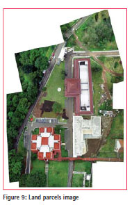
The problems that may arise in the determination of the distance and angle of each photo image is synchronization between photo taken occurrence/ exposure with distance and angle data retrieval by total station. So it is necessary to consider the UAV design and planning specifically related to the implementation of the photo shoot time by arranging the photographic interval timer in the camera and use a beam signaling LED (Light-emitting diode Emitting) as a cue for surveyors to retrieve the distance and angle data of the camera position on the ground. Similarly, the design of control point distribution must accommodate the relationship among land parcels to be mapped, total station capability and design and nature of UAV. Some examples of aerial photos with its x, y coordinate and z (flying height + instrument height) are listed in figure 8. Pictures recorded still contain distortions in which the circular-shaped pictures/ arched as the effect of the lens. For photogrammetric processing stages, each photograph is calibrated beforehand so that the data has the flat form. The post process of each photograph is presented in the form of a mosaic image as in figure 9.

Control Point Design
Control points tied up photograph to coordinate system on Earth, so that the process of reconstruction of the photo of the vehicle UAV will greatly depend on the quality and the distribution of these control points. In this study, selected control points must be close to the parcels that must be mapped. In order to distribute it in the correct manner, control points location must cover parcel boundaries located in a stable place during measurement, total station range must be considered compared to UAV and for this research, we still avoid undulated topography. In addition to the small area being measured, it is possible to use the terrestrial method in ground control points position measurements.
Conclusion
The UAV technology can be used to map a small area economically, but the quality of the resulting map is always constrained by the geometric accuracy problems as a result of the instability of the vehicle while taking the photos, so aerial photography mapping method using the usual UAV cannot be used to create an accurate map. To overcome these problems, we try to modify mapping methodology, which in this research, is done by integrating vehicle UAV systems photogrammetry with terrestrial systems.
The initial phase should be done is to conduct a study about vehicle design which accomodates the characteristic of total station to determine camera position accurately, a vehicle must be able to stop during a flight, and continue flying smoothly, be stable against wind thrust and the outer body material should be made from perfect reflectors like metal. These specifications facilitate observers on land to get the reflection waves perfectly which is then converted onto slope distance, vertical angle, and the coordinates x, y, z of camera at the end.
The deviation between camera centre and shooting target on UAV body can be ignored, so we can assume that coordinate resulted coincide with coordinate of the photo centre.
Refference
Akhtman, Y. dkk. 2011, MAV-Based Real Time Localization Of Terrestrial targets With Cm Level Accuracy, International Archives of the Photogrammetry, Remote Sensing and Spatial Information Sciences, Vol. XXXVIII-1/C22.
Blaha, M. dkk. 2011, Direct Georefferencing Of UAVS, International Archives of the Photogrammetry, Remote Sensing and Spatial Information Sciences, Vol. XXXVIII-1/C22.
Cunningham, K. dkk. 2011, Cadastral Audit and Assesments Using Unmanned Aerial Systems, International Archives of the Photogrammetry, Remote Sensing and Spatial Information Sciences, Vol. XXXVIII-1/C22.
Eisenbeis, H. 2011, The Potential Of Unmaned Aero Vehicle For Mapping.
Stoter, J. dan Oosterom P.V. (2006), 3D Cadastre In An International
The paper was presented at FIG Congress 2014, Kuala Lumpur, Malaysia, 16-21 June 2014.


 (3 votes, average: 3.00 out of 5)


Leave your response!