|
In this paper, the UAV mission and the data processing steps to generate a 3D model of the NUS (National University of Singapore) campus have been described
|
|
 |
Rongjun QIN
|
PHD student of ETH,
|
Singapore ETH Center,
|
Singapore
|
|
|
 |
Prof em Dr Armin GRUEN
|
Principal Investigator,
|
Future Cities Laboratory,
|
Singapore
|
|
|
 |
Dr Xianfeng HUANG
|
Researcher,
|
Singapore ETH Center,
|
Singapore
|
|
Nowadays researchers and various users are very interested in urban applications at large scale, where small UAVs are very useful. In Photogrammetry, UAVs represent a very fl exible and low-cost platform which reduces data acquisition time and provides for high resolution and high accuracy data for small area modeling. Currently, there are increasing demands on urban applications such as environment monitoring, accurate DTM for fl ood simulation and highly accurate building modeling for architectural usage (Gruen, 2012). In this paper, we report about a pilot project of using UAV technology to build high resolution urban models at large scale. We performed this mission in a quite complex urban area in the tropical city of Singapore with a Falcon 8 octocopter, developed by Ascending Technologies GmbH, with an off-the-shelf camera Sony Nex-5.
Most of the UAV applications are performed in suburban or rural areas, such as cultural heritage sites (Eisenbeiss et al., 2005, Remondino et al., 2009), suburban mapping, and agriculture monitoring (Lin, 2008; Gruen, 2012), in which the take-off and landing places are quite controllable. However, little work is reported about mapping urban areas with UAVs. On one hand, it is hard to control the landing and take-off in urban areas, on the other hand, the regulations of air control or even police/military are quite strict for drones fl ying over important facilities, infrastructures, pedestrians, since safety is the most important concern for air regulations. Our fl ight mission was approved after a 6-months period of evaluation. However the fl ying height was restricted to 150 meters. This produced 857 images with very complex scenes and large parallaxes between images. Moreover, the mission had to be divided into multiple fl ights because of the poor battery capability and limited operating distance of the UAV, which results in gaps and irregular overlap on the borders of each fl ight. Geo-referencing these images with a complex geometry turned out to be a challenging work.
In this paper, we report about the difficulties encountered in the data acquisition stage, including various aspects of flight planning, selection of take-off and landing positions, data pre-processing, triangulation, bundle adjustment, 3D modeling, and then introduce our solutions to solve for these steps. In summary, our contribution in this paper is three-fold: 1.We describe the advantages of using UAVs as a mapping and modeling tools for large scale urban mapping and modeling, and list the potential problems and solutions in the practical work, 2. We compare the performances of different commercial and non-commercial software packages in geo-referencing high resolution UAV imagery with large parallaxes and slightly unconventional network structures 3. We analyze the drawbacks of the chosen methods in the mission and provide suggestions for smoother procedures in UAV modeling in dense urban areas.
Data acquisition and data cleaning
The modeling area covers the main campus of National University of Singapore of approximately 2.2. This may not be a large area in mapping, but considering the fl ying height of 150meters and a camera constant of 16 mm with an off-the-shelf camera, we obtained 857 images in total. There is another restriction concerning the flight: the octocopter is not allowed to fl y across the major public roads and should stay strictly within the campus boundaries, which splits the whole area into 3 parts (Figure 1). This required the flight path to follow the border of the campus closely.
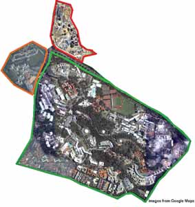
Figure 1: The NUS mapping area. Different colors show different area separated by roads.
The AscTec Falcon 8 is used for the mission. It is a two-beam octocopter with 4 rotors on each side, powered by battery. It has a build-in GPS/IMU, a barometer, electronic compass and a stabilizing system for both the camera and the platform. It has up to 300 meters remote controlling distance with a maximal operation slot of 20 minutes.
Comparing to fixed-wing platforms, it has several advantages:
1. It does not need a runway or ejection devices.
2. The take-off and landing space can be relatively small and confined.
3. The mission can be terminated directly when unexpected situations happen, such as strong wind, unexpected rain or the approaching of another flying object.
4. Image acquisition can be done in a discrete mode by hovering when taking images, which can reduce the motion blur during the operation.
However, since the octocopter needs more power to keep operating, one of the biggest disadvantages is the short operation time. In ideal conditions with a flying height of 150 meters, the octocopter can take 6 images with a baseline of 50 (80% overlap) meters in strip direction and 5 strips with a baseline of 65 meters across strip direction (60%overlap) in one flight, in total 30 images. However, due to signal disturbance and unexpected circumstances like strong wind, loss of connection, etc. we only took maximal 25 images per flight for safety reasons, sometimes even less, especially when the fl ight approaches the boundaries of the mapping area.
Take-off and landing
During the practical operation take-off and landing are the most demanding issues. The ideal situation for take-off and landing is on the roofs of houses, if relatively large and open spaces are available(is suggested). However, most of the roofs are not accessible. Since Singapore is a typical tropical country, and there are a lot of complex cooling systems on the roofs, the spaces on roofs are quite confi ned. In this case, the take-off and landing spaces are mostly restricted to the ground: pedestrian ways, playgrounds, parking lots, etc. (Figure2). During the take-off and landing, the biggest challenge is to avoid large tropical plant canopies. Therefore we used the manual mode for take-off and landing for a more fl exible performance, and then switched to automatic waypoint mode after the octocopter rose to a certain height.
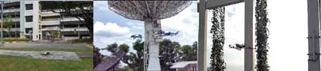
Figure 2: Examples of take-off and landing in confined urban areas
Electro-magnetic disturbance
Due to the complex infrastructures with different functionalities in urban areas, which may create electro-magnetic disturbances, the loss of signal happens quite often. In this case, the pilot needs to move around for an appropriate angle and distance to get the signal back. Therefore, it is suggested to perform the operation early in the morning, when less human activity and radio disturbances are involved. Our data acquisition took 3 days of field work, consisting of 43 independent flights.
Ideally, the produced images and GPS/ IMU records should match perfectly, but our actual data contained a fairly amount of deviations, which can be divided into two types:
1. The GPS/IMU values do not match the images;
2. More images are taken automatically beyond the planned numbers. Those problems may come from the electro-magnetic disturbances which misguide the remotely controlled signals, or bugs in the system software. Therefore, data cleaning took quite some time. We wrote some scripts to accelerate the process by checking image overlaps, deleting images with too much overlap, getting rid of repeatedly taken images, and detecting GPS points which deviated too much from the mean position of the block. Data cleaning fi nally resulted in 857 images out of 929 raw images with corresponding GPS/IMU records, which are shown in Figure 4.
GEO-Referencing
Camera and calibration
The Sony Nex-5 is a mirrorless interchangeable-lens camera, with an image dimension of and a pixel size of in both x and y directions. We use its original lens with a fixed focal length of 16 mm. However, the focusing cannot be fixed and it will automatically focus for each single shot. This camera is well commented in photography, but as we found, the lens has a fair amount of colour refraction, leading to blurring problems in the image corners (see Figure 3). The camera calibration was done in our lab with the software package I-Witness, using the point cloud calibration method (Remondino, Fraser, 2006). The process of camera calibration is fully automatic. After calibration a re-projection error of 0.24 pixels is obtained.

Figure 3: Blur in image corners of Sony Nex-5
Geo-referencing
Our geo-referencing process was divided into two stages: 1. Test the triangulation and bundle adjustment with a small subset of all images of this mission. We took the images from one fl ight as a small subset. To include more GCPs for the test we added four more images in the block corner (Figure 4, highlighted in yellow), 2. Try to do the geo-referencing of the full block with different software packages according to their performance in the small block. The small block tests were performed because it is easier to analyze data in a small dataset. We assumed that if a software package will fail with the small block it will inevitably also fail with the full block. For the full block, we acquired 39 control points with Trimble GPS, with an accuracy of 2 cm in x, y direction, and 3 cm in height. The distribution of the GCPs is shown in Figure 4. In the small block triangulation, points 18,19,20,21 are used as GCPs and
the others are used as check points.
Table 1. Small block accuracy analysis of navigation data. The measured exterior orientation parameters are compared with those from bundle adjustment

We also used the small block for an accuracy analysis of the measured exterior orientation parameters. For this purpose we compared the GPS/IMU measured values with the results from bundle adjustment, which were considered the correct values. Table 1 gives the results of this analysis. We can see that the positional values, as determined by GPS, have maximal values at 4.7, 9.1, 3.2 m for X,Y,Z. But they include a large bias (shift), which, if removed, gives coordinate accuracies for X, Y, Z of about 1 m. The attitude values have maximal deviations of 12.9, 9.2, 3.1 deg for roll, pitch, yaw, and the removal of a shift bias will improve the standard deviations to 3.8, 5.6, 0.8 deg.

Figure 4: Acquired imagery, control points and check points. Triangle: Control points, circle: Check points. Area highlighted in yellow: Sub-block or geo-referencing test.
The control points are denser in the northern part of the mapping area, which results from the triangulation and bundle adjustment tests for the small block, and those points are then also used to perform bundle adjustment in the whole area. The control point distribution for the full block is not ideal, because, due to occlusions by tropical vegetation and other objects, the optimal locations could not be realized. We performed the geo-referencing of the small block with several pieces of commercial and non-commercial software. Most of the software tested in our mission worked relatively well and we obtained an accuracy of about 5 cm in horizontal, and 5-8 cm in vertical direction. However, when it comes to the full block we are running into problems with geo-referencing, which will be shown in the next sections.
Leica Photogrammetry Suite (LPS)
LPS is a popular commercial software package for geo-referencing due to its easy-to-use interface and compatibility with a variety of sensors. This software is not specifi cally designed for UAV imagery. LPS has two modes of tie point measurement: 1. given an estimation of the exterior orientation parameters, LPS will look for corresponding points along the computed epipolar line by correlation methods; 2. Measurement of 3 or more points per pair manually as seeds, LPS will generate additional tie points from these points. The fi rst mode depends on the quality of initial exterior orientation parameters. We imported the recorded GPS/ IMU data as the initial exterior orientation parameters, but it failed because of the poor quality of this data (compare Table 1). The second mode could be a valid way when the dataset is small, but it is not possible to manually measure the tie points on 857 images. Therefore, we wrote a separate program to generate tie points with the Sift operator features (Lowe, 2004): it first generates Sift features, and looks for neighboring images of each image by the recorded GPS position. Image matching is applied with Sift features in the neighboring images. Finally a Ransac algorithm (Zuliani et al., 2005) based relative orientation is performed to orient all the images for detecting blunders and a LPS-formatted tie point file is output. After the tie points stage, we measured the controls points manually and run the bundle adjustment. We used selfcalibration by releasing focal length, principle point and radial distortion. This works well with the small test data set, but it produces unacceptable results for the full dataset. The residuals in check points of the full dataset are shown in Table 2. In Table 2 residuals of some of the check points and the standard deviations of the X, Y, Z residuals are very large, especially in height, which indicates a poor geo-referencing. Here are several possible reasons for this: 1. the tie points generated by the Sift operator may not be well distributed, since it can hardly fi nd distinct features on tree canopies, which sometime takes a large portion of the image content, 2. though we had done the blunder detection in our program, small blunders may still exist.
Table 2: Result of bundle adjustment of the full block with LPS.
Residuals in check points. UAV image footprint ca. 5 cm

APS (Aerial Photo Survey) from Menci Software
APS is a fully automatic software package in which a fairly small amount of interaction is involved. It is originally designed for images acquired by Swinglet from senseFly, while it can also handle images from other UAV imagery, such as Gatewing, Falcon 8, etc. The software requires as input lat/lon/height/heading/ pitch/roll, and if a different exterior orientation system is used, the users need to convert the values externally. However, due to the high automatic workflow, the software provides limited customized settings to adjust the performance of bundle adjustment. In our case it has a fair performance in bundle adjustment in an arbitrary coordinate system, but it does not perform well when GCPs are involved. It leads to a maximal residual of more than 0.5 meters for check points within the small test block. Therefore we only did bundle adjustment of the whole dataset in an arbitrary coordinate system, and fi nally it succeeded to orient all the images with a re-projection error of about 2 pixels.
MATCH-AT and customized tools from Graz University
INPHO helped us to test the Match- AT module with our dataset. It failed to get the required accuracy.
A customized software package from Graz University, which implicitly uses the method proposed in (Irschara et al., 2010, Maurer et al., 2012) was also tested with the dataset. It can robustly orient the dataset and kick out images which have large re-projection errors. It finally oriented 600 images, with a re-projection error of 1-2 pixels. In its current version the software is not able to incorporate the GCPs into the bundle adjustment.
APERO
APERO is an open source tool developed by the French National Geographic Institute (IGN). It is designed for high-end users with different strategies and various parameter confi gurations for bundle adjustment. This tool is a command–line based program working under Linux and MacOs. All the parameters and the strategy related to bundle adjustment are specifi ed in a XML fi le. APERO uses Sift features to extract tie points, and if the matching strategy is not specifi ed, it will start an exhaustive search for neighborhoods. Therefore, for our UAV dataset, we wrote a small script to look for image neighborhoods based on the GPS positions. For each image we defi ned its neighborhood by a given radius. Images whose distances to this image are less than the given radius will be defi ned as neighborhood images. Since there are 3 parts which are separated by roads (Figure 1), the radius should be large enough to cover these gaps.
APERO renders quite acceptable results with free-network bundle adjustment, with an average re-projection error of 0.5 pixels. Then the ground control points are introduced to do a fi nal georeferencing. The result is shown in Table 3.
We can see that after involving the GCPs in the bundle adjustment, we get a maximal residual of 0.15 meters in coordinates (compared to 5 cm footprint). Since we got a very good result in free network bundle adjustment (0.5 pixels), we can exclude measurement problems in tie points. The decrease in accuracy when doing the GCPoriented block may have several possible reasons:
1. Auto-focusing is not modeled (the camera auto-focuses for each image taken),
2. Multiple fl ights with different weather conditions during the 3 days period. Shadows moving and varying signifi cantly,
3. The camera lens has some problems as we discussed in 3.1. Those problems will be investigated further in our research.
Object measurement
We use CyberCity Modeler (Gruen, Wang, 1998) to model buildings on the NUS campus. It is a semi-automatic procedure. While the key roof points are measured manually in stereo mode, the software fits the topology automatically. Giving ordered point clouds measured in a Digital Workstation following a set of criteria, it will automatically generate roof faces and wall faces, where only a small amount of post-editing is needed. It greatly reduces the operation time for constructing building models and can generate thousands of buildings with a fairly small work force. It is also invariant to model resolution, and is able to generate fi ner details on building roofs such as air-condition boxes, water tanks, etc. We used ERDAS StereoAnalyst as Digital Workstation and implemented a converter between StereoAnalyst and CyberCity Modeler.
Table 3: Result of bundle adjustment of the full block with APERO. Residuals in check points.

Since Singapore is a tropical country with a large amount of tree canopy around the city, we face diffi culties in DTM measurement, especially with images taken at low altitude. Green plants lead to many occlusions. Therefore, for areas where there are trees the DTM accuracy of those areas cannot be guaranteed. In this scenario, to build an accurate terrain model even under the plant canopy, extra information is needed. We obtained this information by acquiring Lidar point clouds from a mobile mapping system (RIEGL VMX 250), driving around campus. The Lidar points will then be used to assist building a precise terrain model under the trees along the roads. Intermediate results of the building modeling are shown in Figure 5.

Figure 5: Initial results of NUS campus modeling: (a) one of the UAV images;(b) measured terrain; (c) textured 3D models. (d) zoom-in result.
Conclusions
In this paper, we have reported about our activities of using an Unmanned Aerial Vehicle to perform 3D modeling in urban areas at very high resolution. We have found that several factors in performing such missions are very important:
• Air control restrictions. In some countries fl ight permissions are diffi cult to get. The safety issue is the most essential concern. Besides, restrictions on mapping area boundaries and classifi ed objects create diffi culties and irregularities in flight execution. Restrictions on flying height may result in too many images within a small mapping area, which creates more work load and complexity.
• Take-off and landing positions. It will not be a problem when doing mapping in suburban area, while it is not easy to fi nd suitable places for take-off/ landing in complex urban areas. For this reason the use of fi xed wing UAVs can practically be ruled out.
• The choice of UAV should be related to the dimension of the project. A small UAV is fl exible, and flight permissions are easier to get. But there are limits in battery capabilities and communication links, which may lead to multiple fl ights and large work load.
• The radio disturbances in urban areas frequently intervene with the control signal, which results in loss of link during operation. This further produces errors in the downloaded data (mismatch between image and GPS records).
For data processing, some commercial software packages are available with fully automatic workfl ow for some components of the UAV image analysis process, but most of them are designed for non-expert users who do not have high requirements in result reliability and precision.
In our project we encountered the following problems in UAV acquired imagery:
• Multiple fl ights. Due to the short life of batteries, and limited fl ying distance the whole mission had to be divided into several fl ights (43 in all), which were taken under different weather conditions. This leads to shadow variations (movement of shadows from image to image and intensity changes). Also, the camera kept on autofocusing during the data acquisition.
• Due to the limited GPS accuracy of the system, the overlap varies a lot, sometimes more, sometimes less, especially at each fl ight’s perimeter.
• The navigation data was of poor quality. In the small block we had errors of the perspective centre coordinates of up to 9 m, in attitude values of up to 12 deg. This causes problems in automated tie point extraction, if the image matching is performed with orientation constraints (which is advisable).
• Poor image quality. The camera Sony Nex-5 has lens problems in the image corners (unsharpness and color seams), which may potentially affect the quality of georeferencing and post-products.
The above factors could affect the results of bundle adjustment. Finally, and as the best case, we obtained an accuracy of 6-8 cm, computed from check point coordinates, with APERO. This compares quite well with the pixel size of 5 cm.
This project is still ongoing. We will measure and model the whole campus, including trees and textured terrain. If some of the aforementioned problems are solved we can see the potential of using UAVs for creating 3D models of dense urban areas at high resolution. In the future development, the objective must be to generate a smoother workfl ow for urban applications, with reduced diffi culties in data acquisition and processing. Therefore, we are looking for larger platforms with more operation time, and higher fl ying altitude, which will reduce the number of fl ights, have less occlusions and also be equipped with a higher quality camera.
Aknowledgements
We acknowledge the help of Menci Software in providing an evaluation license for bundle adjustment testing. We also would like to thank Prof. Bischof and Christof Hoppe for running their bundle adjustment for evaluation and INPHO for testing MATCH-AT with our dataset. We also appreciate the help of Dr. Fabio Remondino in providing suggestions for the APERO processing.
References
Eisenbeiss, H., Lambers, K., Sauerbier, M., Zhang, L., 2005. Photogrammetric documentation of an archaeological site (Palpa, Peru) using an autonomous model helicopter. International Archives of Photogrammetry, Remote Sensing and Spatial Information Sciences, 34 (5/ C34), 238-243 (and on CD-ROM). Gruen, A., 2012. Unmanned Aerial Vehicles – from toys to tools. GEOInformatics, January/February, pp. 14-16
Gruen, A., Wang, X., 1998. CC-Modeler: a topology generator for 3-D city models. ISPRS Journal of Photogrammetry and Remote Sensing. 286-295
Irschara, A., Kaufmann, V., Klopschitz, M., Bischof, H., Leberl, F., 2010. Towards fully automatic photogrammetric reconstruction using digital images taken from UAVs. Proceedings International Society for Photogrammetry and Remote Sensing Symposium, 100 Years ISPRS – Advancing Remote Sensing Science
Lin, Z, 2008. UAV for mapping – low altitude photogrammetric survey. International Archives of Photogrammetry and Remote Sensing, Beijing, China.
Lowe, D, 2004. Distinctive image features from scale-invariant keypoints. International Journal of Computer Vision, 60(2), pp. 91-110.
Maurer, M., Rumpler, M., Wendel, A., Hoppe, C., Irschara, A., Bischof, H., 2012. Geo-referenced 3D reconstruction: Fusing public geographic data and aerial imagery. In Proceedings of the International Conference on Robotics and Automation (ICRA), St. Paul – Minnesota (USA), 2012
Remondino, F., Fraser, C., 2006. Digital camera calibration methods: considerations and comparisons. International Archives of Photogrammetry, Remote Sensing and Spatial Information Sciences. 266-272
Remondino, F., Gruen, A., von Schwerin, J., Eisenbeiss, H., Rizzi, A., Girardi, S., Sauerbier, M., Richards-Rissetto, H., 2009. Multi-sensor 3D documentation of the Maya site of Copan. Proceedings of the 22nd CIPA Symposium, 11- 15 October, 2009, Kyoto, Japan
Zuliani, M., Kenney, M.C., Manjunath, M., 2005. The multiransac algorithm and its application to detect planar homographies. IEEE International Conference on Image Processing, III-153-6 |


 (8 votes, average: 2.50 out of 5)


Leave your response!