| Navigation | |
The generation of well geo-referenced floor plans and application in indoor navigation system
This study concentrates on generating the highly accurate floor plans based on the robot mapping technique using the portable mapping |
 |
|
 |
|
 |
|
 |
|
 |
|
In the past few years, Mobile Mapping System (MMS) has been widely used in Geomatics engineering. Using various mapping sensors, such as Light Detection And Ranging (LiDAR), camera and high resolution visible sensors, geospatial information can be easily acquired by a mobile platform. The most common mobile mapping systems work by capturing more than one image which include the same feature point, captured from different perspective, allowing the 3D spatial information of objects to be calculated and measured with respect to the mapping frame (Tao et al. 2001). MMS is also being used with various vehicles, such as automobiles, aircraft, water-based vessels and Unmanned Aerial Vehicles (UAV). More recently, the use of MMS has not been restricted to being mounted on mobile machines. A portable MMS has been proposed which is composed of a Position and Orientation System (POS) module working in conjunction with an image acquisition module, trigger control and data logging module (Chu et al. 2013). This system could be used in some areas that are inaccessible to vehicles.
Because of the increasing demand for accurate indoor maps, MMS has evolved to the next phase: indoor environment. This application would be useful for emergency, indoor navigation, as well as Location-Based Services (LBS), etc. In fact, high accuracy map of indoor environments, once it caught on, would soon become indispensable in indoor navigation and LBS. In general, building blueprints are not easy to access; determining and NAVIGATIONevaluating the absolute accuracy of these blueprints are a logistical nightmare. In robotics research, most robotic navigation tasks are based on the building maps, therefore, methods for generating relatively reliable floor plans has become an important topic (Okorn et al. 2010). Robot mapping systems focus on real time localization, sensing and measuring the environment at the same time; as a result, Simultaneously Localization and Mapping (SLAM) algorithms are widely used in robot applications.
After analyzing previous researches, most robot mapping systems concentrate on developing high efficient SLAM algorithms or using different platforms to implement the SLAM. However, these floor plans generated by the robot mapping are limited to certain mapping system and therefore, lack of generalization. Even though the maps are produced by the same system, it requires extra works to relocate the position and reorientation manually in order to reuse the produced maps. Besides, floor plans generated by the SLAM are hard to evaluate the accuracy and can’t directly be used in other applications. The main problem is that these floor plans are not in the standard coordinate frame and therefore it is tough to use. This study proposes the modules for generating indoor floor plan that can transfer the local map reference in robot system into well geo-referenced map. This kind of map can be applied for various seamless applications, such as the navigation system from outdoor to indoor. Also, this study uses the sketch maps of building to create the indoor floors map compared with the maps by SLAM. To evaluate the absolute positioning accuracy and rectify the indoor floor plans from different platforms, this study built the testing and calibration field based on the control survey to analyze each result for purposes of cross validation.
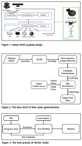

Indoor MMS design and implementation
To implement the indoor MMS, the payload design of this study is divided into two parts, namely localization and mapping. In the localization system, GPS/INS (Inertial Navigation System)is the primary integration system that generates the global position information for the mapping system and enables the user to move seamlessly from outdoor to indoor environments (and vice versa) based on the produced floor plans with a global coordinate system. In the design of this localization system, aiding information, such as heading data from a digital compass, height difference calculated based on atmospheric pressure, and even the velocity and attitude states determined from sequential images, is used to update the navigation filter as well. The mapping system, which includes a laser scanner and an RGB-D sensor, is used to derive the scan data. It is important for the mapping system to conduct preprocessing and calibration before the mapping process to improve accuracy. The data from each scan is combined with position and attitude information in order to register the different datasets together with the position and attitude feedback to the navigation filter. This common payload is designed not only for robots and UAVs, but also for human carriers and other mobile platforms. The payload design is presented in Figure 1.
Methodology
SLAM has been developed for many years, and most algorithms achieve the robust performance on mapping system as well as localization. The generated map often used in navigating the robot and implementing the autonomous motion planning. In this study, the issued problem is that if user wants to update the map or implement the motion planning with known map, it needs to take extra efforts to initialize the position and orientation. It is also known as global localization problem that puts the robot into the known environment and has to localize itself from scratch. The primary issue is that the map is often generated in different reference frames. This problem also occurs when users apply the robot map on different applications. Another problem is that without any landmarks or absolutely aiding information, the accuracy of robot mapping is degraded with time. Therefore, this study proposes the novel map rectification process to rectify and transfer the raw map into the global frame with reliable scale and accuracy. Figure 2 shows the floor plan generalization processes and the detail is described below.
Hector SLAM
SLAM is a common solution that senses and recreates the map of an unknown environment and simultaneously tracks the position and attitude of the platform in robot research. The core integrating algorithms are classified into three paradigms, Kalman filters, particle filters and graph-based processing. In SLAM applications, most of algorithms rely on environmental landmarks and the sensors’ raw-data which are integrated into the SLAM model. For the robot map, occupancy grid maps cut the environment into the small cells, each of which includes different attributes to represent the environment. An occupancy grid maps record the whole environment information that sensors observe and transfer it into the occupancy grid. This study aims at using grid-based SLAM algorithms, Hector SLAM, to generate the floor plans.
Due to the rapid development of mapping and localization sensors, most robots are equipped with a payload of a small laser scanner and MEMS IMU. Hector SLAM is one of the SLAM algorithms developed for laser scanners (Kohlbrecher, 2011). The main differences between these two SLAM algorithms are the 6 DOF motion estimation without odometry and scan-matching method. Figure 3 shows a flow chart of Hector SLAM process. This means the mapping system doesn’t have to be mounted on at mobile robot; it could be mounted on UAV, human or other platforms without odometer.
The estimated pose information is an important parameter for scan-matching; it improves the performance. In addition, scan-matching also gives the posterior information to enhance the navigation results. Scan-matching plays a significant role in Hector SLAM. In the process, the data from the laser scanner is aligned with the map or other observations. Based on the high accuracy of laser scanners, with low distance measurement noise and high scan rates, scan-matching provides 2D pose estimation for the navigation filter by registering each piece of scanned data and aligning it with the existing map. This approach is based on the optimization of aligning the endpoint of the scan data and the existing map. The basic idea is follows the Gauss-Newton approach from (Lucas et al., 1981).
Map rectification
In order to deal with the scale and deformation problems of generated map from different mapping systems, this study proposes the new method to refine the map and also implements the coordinate transformation to generate the map in global frame. The flow chart is shown in the Figure 4. In the beginning, the local map and control points are located in the same coordinate system. For rectifying the map, map rectification uses the affine transformation that includes 6 parameters, two translations, two scale, rotation and shear. In this transformation, it needs to select at least three tie points from control survey in order to calculate 6 parameters and eliminate the deformation problem. Therefore, there is a significant correlation between tie points selection and the accuracy of rectified map. Tie points should be widely and uniformly placed at distorted area to control deformation. Finally, ![]()
Experiment
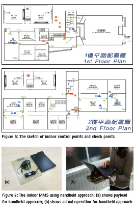
Because the accuracy of the indoor map is not easy to assess and evaluate, this study adopts an indoor control survey for the mapping experiments. Before conducting the experiments, a control survey was established by using angle and distance measurements observed by a high accuracy device. A sketch of the control survey is shown in Figure 5; the triangular points represent the control points, and the green points are the check points located in the building’s corners for evaluating the floor plan. These check points measured by the control survey are represented as the building’s boundary features to compare with floor plan. Total experimental area is about 1300 square meters, the width is about 30 meters and the length is about 60 meters.
In this experiment, we deployed laser scanner (UST-20LX) using handheld approach to analyze and evaluate the performance of indoor floor plans. The configuration shown in Figure 6.
Results and discussions
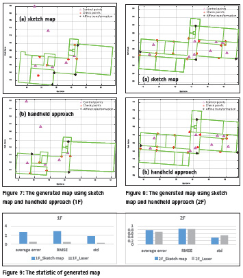
After the scan of the laser scanner, the raw map of the environments are derived. Since the distroted and the scale problems mentioned above, we continue with the map rectification. Figure 7 and figure 8 show the comparison between generated maps. The triangular points stand for control points, the red points are the check points, and black points are used to do the affine transformation. Others can be the index of the accuracy analysis.
Take a look at relative positions of the points and the maps, as the check points are all designed in the corner, most of the points in laser scanner receiving maps match the corners that they should be. On the other hand, the maps generated by sketch maps have more displacements from the positions that the points belong to. In figure 7, the scale problem is obvious in the right part of both figure. The length of the space is range from 20 m in sketch generated map to 30 m in laser scanner received map. In figure 8(b), there is a trend for the check points and the positions they should locate. All of the should-be corners are in the right of each corresponding check points. It shows the posibility to calibrate this problem with the similar situation. However, the conditions in figure 8(a) are too random that depending on the sketch maps creator. To be more convincing, this paper looks deeply into the values and do some calculations. From the comparisons of figure 7 and figure 8, the coordinates turn out to be the calculations of the points’ accuracy. The indexes include average errors, standard deviation and RMSE. Figure 9 shows the computation in histograms for 1st and 2nd floor respectly. Each histogram has the comparison of generated maps between sketch map method and handheld approach.
We can tell from figure 9 that most of the blue histograms get higher than the gray ones. That is to say, almost all of the computations support laser scanner has better result than the method of sketch map. Besides, the accuracy reaches the goal within 1 meter. Since the outcomes from sketch map has a better results in 2nd floor than in 1st floor. It’s assumed that the more check points, the more possible to get greater calculations. As standard deviation results always preferable than RMSE outcomes, the problem to get well geo-referenced floor plans should be considered.
Conclusion
In order to improve the accuracy of the indoor floor plans generated by sketch maps, this study turns to the robot mapping technique with the portable mapping system to produce highly accurate floor plans. Existed sketch maps should be convenient but the accuracy isn’t quite suitable for indoor navigation. However, we know that indoor environment is relatively narrow than outdoor environment. Therefore, the accuracy must also be in a rather strict level.
Based on the map rectification approach using the affine transformation, this study solves the scale and deformation problems out of the former method. With the calibration field built by traditional outdoor control survey method, the absolute accuracy of indoor floor plans can be evaluated. At the same time, this study has been able to illustrate the portable robotic mapping system really working out well. Since the average errors, RMSE and standard deviation in this study are all within 1 meter, it goes without saying that the approach certainly meets the usage for indoor navigation maps. When compare with the sketch map method, it also gets better accuracy. Finally, this study clearly demonstrates that the building floor plans reach 1-meter absolute positioning accuracy by proposed portable mapping systems and rectified sketch maps combined with the map rectification.
Acknowledgement
The authors would acknowledge the financial support provided by the Ministry of Interior of Executive Yuan in Taiwan.
References
[1] Tao, V.C.; Li, J. (2001). Advances in mobile mapping technology. International Society for Photogrammetry and Remote Sensing (ISPRS) Book Series: Taylor and Francis Group: London, UK.
[2] Eisenbeiss, H. (2004). A mini unmanned aerial vehicle (uav): System overview and image acquisition. In: Proceedings of the International Workshop on Processing and Visualization Using HighResolution Imagery, Pitsanulok, Thailand.
[3] Neitzel, F.; Klonowski, J. (2012). Mobile 3d mapping with a low-cost uav system. In: International Conference on Unmanned Aerial Vehicle in Geomatics (UAV-g), Vol. XXXVIII-1/C22, pp 39-44.
[4] Chu, C.H.; Chiang, K.W.; Lin, C.A. (2013). The performance analysis of a portable mobile mapping system with different gnss processing strategies, Proceedings of the 26th International Technical Meeting of The Satellite Division of the Institute of Navigation (ION GNSS+ 2013), Nashville, TN, September, pp 689 – 703.
[5] Okorn, B.; Xiong, X.; Akinci, B.; Huber, D. (2010). Toward automated modeling of floor plans, Proceedings of the Symposium on 3D Data Processing, Visualization and Transmission Paris, France, 5/17.
[6] Grzonka, S.; Grisetti, G.; Burgard, W. (2009). Towards a navigation system for autonomous indoor flying. In Robotics and Automation. ICRA ’09. IEEE International Conference on, IEEE: Kobe; pp 2878 – 2883.
[7] Fallon, M. F.; Johannsson, H.; Brookshire, J.; Teller, S.; Leonard, J. J. (2012). Sensor Fusion for Flexible Human-Portable Building-Scale Mapping. Intelligent Robots and Systems (IROS), IEEE/RSJ International Conference on, IEEE: Vilamoura, pp 4405-4412.
[8] Kohlbrecher, S.; von Stryk, O.; Meyer, J.; Klingauf, U. (2011). A flexible and scalable slam system with full 3d motion estimation. In Safety, Security, and Rescue Robotics (SSRR), 2011 IEEE International Symposium on, IEEE: Kyoto; pp 155 – 160.
[9] Grisetti, G.; Stachniss, C.; Burgard, W. (2007). Improved techniques for grid mapping with rao-blackwellized particle filters. Robotics, IEEE Transactions on 2007, 23, 34 – 46.
[10] Kaplan, E.D. (1996). Understanding gps: Principles and applications. Artech House.
[11] Wolf, P.R.; Ghilani, C.D. (2006). Elementary surveying: An introduction to geomatics. Pearson/Prentice Hall.
[12] Van der Heijden, F. (1995). Edge and line feature extraction based on covariance models. Pattern Analysis and Machine Intelligence, IEEE Transactions on 1995, 17, 16-33.
[13] Chiang, K.W.; Liao, J.K.; Tsai, G.J.; Chang H.W. (2015). The performance analysis of the map-aided fuzzy decision tree based on the pedestrian dead reckoning algorithm in an indoor environment, TN, December.


 (No Ratings Yet)


Hi, th blog is very informative but this is about MMS(mobile mapping system) now the technology got improved many using indoor positioning and navigation app for Museums, Shoppiing malls, Resorts, Hospitals etc. Or more you can explore http://pigeon.srisys.com/
Leave your response!