| Navigation | |
Self driving and flying robots
While no localization technology claims to work in every possible environment, use of combination of multiple sensors is the path forward to a fully autonomous future |
 |
|
Picture this – In a not so distant future, you are a self-employed small business owner selling organic homemade lip balm through e-commerce sites like Amazon or Flipkart. You wake up in the morning to see that a customer across your city has placed a large order for a large shipment of your product. While having coffee, you pack a cardboard box with your product, walk outside to your backyard sipping coffee and keep the packaged box, ready to be shipped, on the lawn and open up your e-commerce portal account and click ‘Ready for Collection’. This simple click starts a domino effect of a chain of events that will ensure your package safely reaches its destination and you get your payment. After placing your request for pickup, at an e-commerce facility not so far from your house, your delivery request is received and their Warehouse Order Management (WMS) system gets to work. An autonomous drone (flying cargo delivery robot) wakes up and flies to your backyard within ten minutes, skipping most of the early morning traffic and locates your address (and the pickup package) with pinpoint accuracy and gently lands on it. The drone then secures the package in its payload bay, lifts off and heads back to the e-commerce facility and gently drops of the package to an automatic conveyor belt that takes it to a dispatch bay. The package is picked up by an autonomously operating ground robot that scans the address label using a pair of stereoscopic cameras and drives to a nearby fully autonomous truck and places the package in the truck’s cargo hold. Once the truck is fully loaded, it starts from the warehouse facility and self-navigates itself to another ecommerce facility across the city. The same process is reverse repeated and the package is delivered to the final destination. Sounds science fiction? It’s a lot closer to reality than one would think. Let’s understand some of the localization and navigation technologies that are making this possible today.
In order to understand how robots navigate and accomplish the above tasks without any human intervention, let’s look at the technological advances through a magnifying glass and understand:
▪ How the drone is able to navigate and fly fully autonomously with pinpoint accuracy.
▪ How the small ground robot is able to navigate precisely indoors where no GPS is available.
▪ What advances are enabling the fully autonomous truck to drive itself through heavy traffic without incident.
Indoor Robots and Visual Inertial Navigation
In the example use case above, the indoor ground robots that are required to precisely localize and navigate through an indoor warehouse to deliver goods and packages cannot rely on GPS (GPS does not work indoors) and often use other forms of SLAM (Simultaneous Localization and Mapping) techniques for navigation such as WiFi, Bluetooth or RFID positioning. In most cases, they require some form of support infrastructure deployment such as Wifi Routers, Bluetooth Sensors or RFID tags to be deployed in warehouses. Often, these are cumbersome and can significantly drive up cost and deployment time. Advances in newer techniques that are using commercial off the shelf (COTS) sensors such as low cost cell phone components and cameras have enabled precise indoor localization & navigation, for robots and factory automation (forklifts, cranes, etc.) without the need for additional underlying support infrastructure. Using a low cost consumer grade pair of cameras, stereoscopic vision sensing and navigation is gaining traction because it not only eliminates the need for any such support infrastructure, but also provides the ability to be useful in other auxiliary vertical turn-key features such as inventory barcode scanning or accurate inventory mapping. Stereographic vision sensing involves placement of a pair of cameras to mimic the human eyes. By placing these at a certain distance to each other, they are able to provide an accurate 3D perception of objects and use to find specific points in 3D space.
How does Indoor Localization using Visual Inertial Navigation Work?
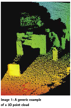
Visual Inertial Navigation typically blends two positioning techniques – Visual Inertial Odometry which uses Dead Reckoning to produce a POSE (Position & Orientation) estimate by using raw measurements from the inertial sensor and visual cues. A second Map-matching step that relies on known surveyed external landmarks to correct the predicted POSE to produce a better corrected estimate. The map-matching step typically makes use of a 3D point cloud that is generated using vision or LIDAR sensors. A generic example of a 3D point cloud is shown in image 1. As we humans see the world in color and depth, sensors allow robots to visualize the world and objects in a similar 3D depth representation that gives them a sense of ‘awareness’.
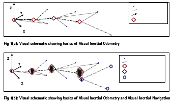
However one of the challenges of just using Visual-Inertial Odometry is that the POSE error estimate grows over time as the distance traveled from a known point (origin) increases. This is due to accumulation of residual errors in the measurements. As seen in the image below, the position error, as shown by a scatter plot, increases with distance from origin and when the system gets a known external landmark it does a POSE adjustment and ‘snaps’ or corrects itself to the accurate position by matching the known landmark to a pre-existing copy of it that it already has during a previous mapping run.
This can be demonstrated by a simple experiment that you can do yourself at home (Image 2).
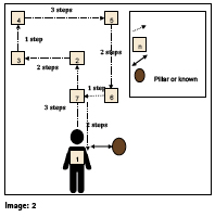
Stand at precisely one arm distance from a known object such as a pillar with enough open space ahead of you. Touch the pillar such that your fingertips are just touching it.
With your eyes open and using approximately same paces, walk three steps to waypoint [2].
Now turn left 90 degrees and walk to waypoint [3]. Follow the track as shown from waypoints [3] through [7] to return back to your original position [1].
Once back at your original position, turn around 180 degrees and see how far you are from your original position – by extending your arm and measuring how far your fingertips are from the pillar as compared to when you first started walking.
You will notice that you would be roughly in the same position that you first started with a little bit of variation or difference. Now attempt to do the experiment again, this time with your eyes closed (use caution and have someone accompany you as a safety precaution). Once you finish retracing your entire path and have ended up in the starting position (and orientation), open your eyes. What is your observation this time?
If you were able to accurately get back to the precise position from where you started, try repeating the experiment by doubling or tripling each distance segments. You might notice that in the second experiment with your eyes closed, you should be within a reasonable distance of your starting point but not exactly at it and there will be some error in your position. This type of navigation is called Dead Reckoning. The reason for the error in your position is due to the fact that as you were tracing your path and measuring your steps or paces, there was a minor amount of error introduced in each step or direction (after you completed each straight line path). These minute errors accumulate over time and incrementally add up to cause a drift in your position.
Visual-Inertial Navigation is now possible using low cost stereographic cameras on robots that mimic the human eyes. These pair of cameras use visual cues and points in 3D space along with inertial measurements to create a POSE estimate that is pretty accurate. As we have seen how accumulated dead reckoning errors grow over time, navigation algorithms correct for the deviated position when a particular known external landmark (already stored in memory during a previous space mapping run) becomes visible. This new measurement is used by the navigation filter to correct (or reset) the POSE uncertainty thereby reducing the overall position error. One of the fundamental aspects about Visual- Inertial Navigation is that it relies on a Local Coordinate Frame or Frame of Reference. That is, in the above experiment example that you tried, your orientation was always measured with respect to your starting point (origin). This type of localization is great when you want objects or robots to localize and navigation in a particular custom frame of reference – example if a particular e-commerce facility designates a particular point inside the factory structure as the origin, then all the machines operating within that facility can use the same frame of reference to navigate.
Outdoor Robots and Global Navigation Satellite Systems (GPS/GNSS)
In our above example, an outdoor package delivery drone is tasked with flying to a customer’s address. As the customer requests for pickup, the E-Commerce WMS places the order and converts the pickup address (House number, street name, city, state, etc.) into precise GPS coordinates (Latitude, Longitude and Altitude) that the drone will now fly to. Advances in GPS / GNSS (Global Navigation Satellite Systems) technologies have allowed for precise centimeter level position capabilities that unlock such applications. One of several challenges faced by GPS is the fact that regular GPS / GNSS receivers that are available in mass market applications such as cellphones and wearables do not use precise positioning techniques and are limited in position accuracies of a few feet (best case). Position accuracies degrade rapidly in challenging environments such as downtown urban canyons, and could easily be tens of meters. For the longest time, inherent errors in GPS did not allow for robust sub-meter positioning accuracies, however, with the advancements in techniques such as Real Time Kinematics (RTK) and Precise Point Positioning (PPP), GNSS receivers these days are able to easily output positions within a few centimeters.
How does regular & precise GPS work?
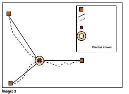
Let’s do another simple experiment that you can try at home to see how GPS and Precise GPS (RTK / PPP) work. Using 3 pieces of strings and tape, we will demonstrate how GPS should work in an ideal world free of any position error sources to give us perfect position. GPS works on the basic principle of Trilateration – knowing the exact location of 3 or more objects fixed in space, one can accurately determine the position of any other object that is placed within their collective sphere(s) of influence of the 3 static objects by determining the precise distance to those 3 objects and finding the point of intersection of the spherical arcs. This can be demonstrated by the simple string experiment as shown below where the pillars or fixed objects represent the GPS / GNSS satellites orbiting our planet.
Take 3 pieces of string and a tape (image 3). Stand at a location in your house or office that is approximately equidistant from 3 fixed objects such as pillars.
Take the first string and tape it to the first pillar at the intersection of the pillar and floor such that there is no gap between the floor and the string.
Now walk up to your original position while keeping the string completely taut (no slack) touching the ground and tape it on the floor at your original location.
Repeat steps 3 & 4 for the remaining strings.
Knowing the precise distance X,Y & Z from the pillars, one can precise calculate the location of the observer in a common coordinate frame.
However, in real life, unfortunately due to a lot of error sources, the distances measured to each GNSS satellite are not accurately measured as they have a lot of error in them due to various sources of error such as atmospheric (Ionospheric & tropospheric), local (multipath), Relativity, Clock Error, etc. that lead to a diluted distance measurement. To understand how errors affect positioning, from our above experiment, let us now introduce a bit of slack in each string (say about 5 – 10 cm) such that the strings now have some wiggle room are are not taut (shown by dashed lines). Now, if you were to take the 3 ends of the strings and start drawing a spiral with increasing diameter such that it creates a circular area within which each string is taut at a particular orientation, this circular area is the positioning error that is introduced due to the various error sources.
This phenomenon explains why sometimes when you use a GPS based taxi or ride sharing app in a downtown city area with tall dense buildings, often your GPS shows you a location that might be different from your actual location and you have to then call and coordinate with the driver. In this case, typical1 consumer2 grade GPS / GNSS receivers do not use error correction techniques that can remove such errors to offer precise Decimeter or Centimeter level positioning accuracies. The basic principle of Precise GPS / GNSS (such as RTK or DGNSS) relies on the core assumption that if you already know the precise location of a particular GNSS receiver (such as one installed in a high quality Geodetic reference or weather monitoring ground station) that is situated within relative close proximity of the user’s GPS / GNSS receiver, then the errors in both of these units will be roughly of similar magnitude. Using this assumption, one can reverse calculate the position errors being observed the Ground stations (whose precise Latitude, Longitude and Altitude is already known with historical data) and send them via corrections to the user’s GPS receiver that can then apply these error corrections to improve the position accuracy. The same principle is also used in other differential techniques such as Network RTK or Precise Point Positioning (PPP). As commoditization of precise positioning GPS technology continues to occur, more and more low cost RTK and Differential GPS / GNSS receivers are entering the market and are starting to offer low cost high accuracy position solutions.
1 There are new receivers that are just entering the consumer market that will be much more accurate.
2 GPS / GNSS receivers used in consumer applications such as smartphones, smart wearables or activity monitors.
Fusion of various positioning technologies for varying application environments
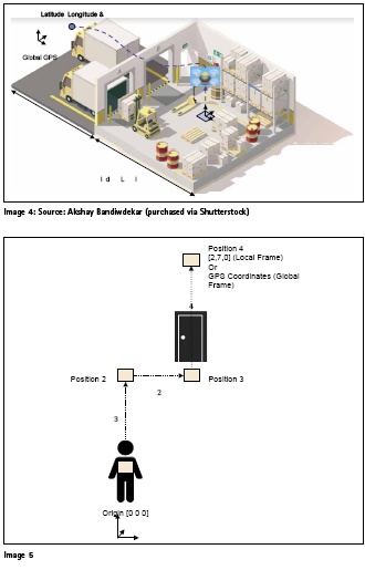
Now we have looked at how Indoor and Outdoor positioning technologies are fundamentally different, let us explore how some applications require use of both of these and pose a particular systems engineering problem that is created due to the use of different coordinate frames in each respective technologies. From our above example use case of the drone or UAV that is situated in an e-commerce warehouse and flies to your backyard to collect a package, it first wakes up in an indoor environment where GPS signals are unavailable and all indoor flying is done via Visual-Inertial Odometry. Further as seen in the image 4, the drone navigation system quickly needs to transition to a GPS global coordinate frame as it now seeks to automatically find your address and when returning with the package it needs to transition to the local frame without incident.
This can be demonstrated in a simplified manner by the image 5, where let us assume that a person starts off indoors from their living room and transverses the path to point [4] via waypoints [1], [2] and [3]. As they start navigating from point [1] in a local coordinate frame, their position coordinates are relative to the starting point (local coordinate frame) – especially if they are using stereographic visual-inertial navigation and transition to a global coordinate frame once outdoors as they switch to their phone’s GPS. While this problem might seem straightforward for most people, it actually presents a lot of challenging scenarios when one starts to think about complex environments where robots have to navigate, such as a fully autonomous self-driving car that is exiting a closed or underground parking garage or a delivery drone that is trying to enter and navigate an e-commerce facility loading dock full of people, trucks, forklifts and other equipment.
As more and more autonomous and robotic applications start emerging, the applications and manufacturers that solve the overall systems problem using multiple localization sensors (GPS, Inertial, Stereographic Visual, LIDAR, Ultrasonics, Radar, etc.) working seamlessly together using sophisticated and robust sensor fusion techniques will emerge as winners. While no localization technology claims to work in every possible environment, use of combination of multiple sensors is the path forward to a fully autonomous future.
Acknowledgments
Dr. Adam Harmat, Senior Software Engineer – area17, Guidance on figures 1(a) and 1(b)


 (No Ratings Yet)


Leave your response!