| GNSS | |
Robotization of precise levelling measurements
The central idea of the proposed method is that robots move and control levelling instruments and rods. The observer’s work is helped in the aiming of rods and the recording of observations |
 |
|
Precise levelling is a traditional method to measure height differences. Currently work stages are performed by hand. In this paper the challenges of robotizing precise levelling measurements are discussed. The difference to the existing solutions would be that robots handle the levelling instruments and rods, and rod readings are remotely recorded via Bluetooth connection.
An automated levelling system would be possible to construct due to the improvement of levelling instruments and robotics. During previous decades, Zeiss Ni 2, Ni 002 (Hüther, 1973) and Wild NA 2000 (Ingesand, 1990) have been major advances. The first automatic levelling instrument, Ni 2, was presented in 1950. It has a compensator pendulum which automatically keeps the instrument’s line of sight horizontal. The description of the level is presented, for example, by Schomaker and Berry (1981). An automatic level Ni 002 is ideal for the motorized levelling method. Due to its aiming solution, observers can read rod readings without leaving their vehicles (Vestøl et al., 2014). A digital level, Wild NA 2000, was presented in 1990. Digital levels record rod readings using images of barcode scales. The aforementioned instruments do not have aiming or focusing properties. The Sokkia SDL1X level (Sokkia, 2009) has an autofocus but the aiming of the rod has to be solved. Using machine vision techniques the aiming problems can be solved. Levelling instruments could be like robotic total stations, which have perfect target searching properties. A robotic total station, Geodimeter 4000, was presented in 1990 (Cheves, 2007) and a total level station, Dini 10 T, was presented in 1995 (Feist et al., 1996).
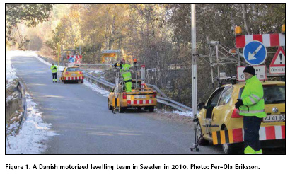
Robotized levelling would be a developed version of today’s motorized levelling, where expeditions have an instrument car and two cars with rod transporting systems, like in the Danish motorized levelling for example (Figure 1). A review of motorized levelling in Nordic countries is presented by Vestøl et al. (2014). The early developments were made in the former German Democratic Republic and the USA (Poetzschke, 1980). To speed up measurements, not only cars but also motorbikes and bicycles have been used as vehicles.
A description of precise levelling measurements
Precise levelling measurements are performed between two stable benchmarks, which are typically placed at the distance of 1–1.5 km. Levelling instruments can reliably record rod readings if the sight distance is less than 50 m, so the measuring has to be made in successive setups. If the team is moving on foot, then it takes about an hour to measure an average length benchmark interval.
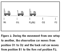
Precise levelling observation is the difference between the back and fore rod readings. Typically, four readings are recorded. For example, the order can be BFFB, where B is a reading from the back rod and F from the fore rod. After readings, the fore rod keeps its position, but the instrument and the back rod are moved to the next position (Figure 2). At the recording moments rods are in a vertical position and invar bands are towards the instrument.
On the equipment in the robotized method
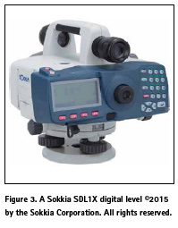
The Sokkia SDL1X (Figure 3) levelling instrument has an autofocus property and its Bluetooth modem enables remotely controlled wireless operations. According to Sokkia (2009), rod readings are recorded in 2.5 sec and it has a precision of 0.2 mm as the standard deviation on a 1 km double-run levelling. A dual-axis tilt sensor alerts the user and disables observations at ± 8.5’. A pendulum compensator with a magnetic damping system has a working range of ± 12’ and a setting accuracy of ± 0.3’’. The Sokkia SDL1X and most collaborative robots have a protection class of IP54. In this class devices are protected against dripping, sprayed and splashed water. Protective covering is needed on the rainy days that provide the optimal weather conditions for levelling. If the protection class is IP67, then robots can be used every day without problems.
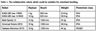
The robot selection criteria are payload (carrying capacity), reach, the robot’s weight and its protection class. All suitable robot models have a good repeatability (approximately ± 0.1 mm), so the exact values are not presented in the table 1. The payload criterion for an instrument robot is dependent on the weight of the levelling instrument SDL1X (3.7 kg). Sokkia levels are used with Sokkia BIS30A superinvar rods, which weigh 5.5 kg.
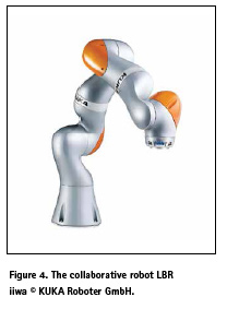
The robots carry a gripper and possibly a rod supporting system, so a payload of 10 kg is reasonable. The cheapest robots could cost less than €35 000, but the prices vary strongly. Some robot candidates are presented in Table 1. A top-end robot for the work would be a LBR iiwa (Figure 4). For the summary of the collaborative robots, see Bélanger (2015) and Williamson (2015).
Collaborative robots can work safely alongside humans. The collision detection system stops movements if an obstacle is detected. In practice, safety requirements can be satisfied with industrial robots using area scanners or safety fencing. The disadvantage is that more complicated solutions can be more vulnerable in field conditions. The outcome is that lightweight collaborative robots are the best candidates for the levelling work.
If lightweight robots are placed onto a car’s roof-rack, then measurements can be performed without any special levelling cars. This would be an important benefit of the method. In principle, it would be possible to change any car into a levelling car. The solution could replace today’s complicated structures (Figure 1).
The robotized precise levelling method
Basic ideas for how robots could control the position and orientation of instruments and rods are presented in this chapter. The gripper (endof- arm-tooling) is installed on the wrist of the robot arm. The exact gripper design is dependent on the technical properties of robots. For a mathematical introduction to robotic manipulation, see Murray et al. (1994).
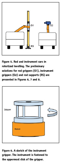
Three robots would be required in the robotized levelling expeditions. One would operate with a levelling instrument and other two with rods. Sketches of levelling cars for robotized levelling are presented in Figure 5.
The challenges in the instrument gripper design
In the proposed method, robots are used as supports for instruments during recordings. Measuring without any extra support is a tempting option, but it is possible that a solution with a pole or more complicated supporting structure is needed. In today’s measurements, instruments are mounted on tripods, but this solution is unlikely to work well with robotized levelling. A gripper sketch is presented in Figure 6. In the gripper, an instrument is mounted on the uppermost disk and the second disk is connected to the robot.
Recording is started when the instrument is aimed at the rod and the barcode scales are aligned to the instrument. The aiming could be based on robot camera solutions. In a manual solution, the camera view can be seen on the controller screen and the target rod can be selected manually. A better solution would be based on machine vision technology (Turek, 2011). Before aiming, it would be possible to compute approximate rod positions. In most cases rods are placed in opposite directions, so that after rotation of 180°, an instrument is approximately aiming at the other rod. After being aimed, the instruments can automatically perform the focusing and recording of rod readings.
Some preliminary solutions for how robots could move rods
Robots can easily move rods between the transporting and observing positions. As a problem is that due to an uneven ground surface, the height difference between the ground and the robots varies in every observing location. There are two points of view on how to solve this problem: the surface can be detected by weight sensors or the collision detection system stops the downward movement.
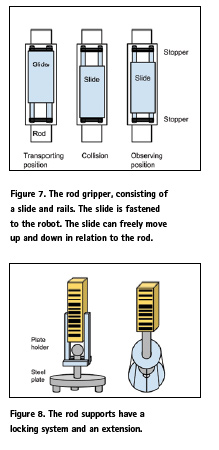
Rod gripper ideas for collaborative robots are presented in Figure 7. The solution is based on round shaft linear motion technology, which is applied for example in the Simplicity linear slides (PCB Linear, 2013). In the solution, there are rails behind the rods and slides affixed to robots. If the slides can move back and forth 10 cm in rails, then most locations could be measured without problems.
Robots could stop the downward movement when a rod reaches the ground. If weight sensors are used, then the movement is stopped when the weight of the carried load vanishes. Without weight sensors the movement is continued until a slide and a lower stopper collide. Due to the collision detection system the movement is stopped quickly. When rods are on steel plates the only force in a vertical direction is the rod’s weight. It is possible that on rough terrain some humancontrolled operations are needed.
In the rod support solutions there is a locking system which fixes together a rod and a steel plate (Figure 8). The idea is that during observations rods can be rotated freely on the plates. In the first solution, the extension can move through the plate holder. In the second solution, the extension is fastened to the rod and it can move through the toroid construction. The extension is on the lower toroid when the rod readings are recorded.
The determination of observing positions
If an expedition moves on foot, then a distance measurer goes on ahead of the other team members and marks the positions. The motorized levelling cars are equipped with measuring devices. In the robotized method, approximate distances and height differences between the cars could be used in position determination.
Sight distances from the levelling instrument to the back and fore rods should be as equal as possible. The maximum allowed sight distances are dependent on weather conditions. On cloudy days sight distances of 45 m can be used.
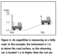
The line of sight is oriented horizontally, so the visibility of rods has to be checked carefully, especially on sloped roads. Naturally, measuring is slower on hilly roads, where more setups are needed. In order to decrease the refraction effect, a minimum accepted rod reading is about 0.5 m above the ground. In the Danish motorized levelling method (Figure 1) there is an extension below the rod that makes impossible to make observations near the ground. To record rod readings reliably, digital levels need some 0.3 m of visible rod. Therefore a suitable maximum height difference between the rod positions is approximately 0.7 m less than the length of the used rods (Figure 9.).
Equal sight distances remove the collimation error from observations. The error is possible if the instrument’s line of sight is not equal to the horizontal plane. Levelling instruments measure distances and it is possible to check the cumulative sum of the distances after every setup. Therefore, it is not dangerous to have different sight distances in a setup if the distance error is corrected during the next setups.
Levelling observations could be used as an independent data set in the calibration of the locating method. The heights and distances can be computed using the rod readings, distances and the instrument’s height above the ground. A distance error in Sokkia SDL1X levels is 1 cm if the distance is less than 10 m. For the distances from 10 to 50 m, it is 0.1% of the distance.
Productivity
The measured distance is dependent on the number of setups and sight distances. In the following example time difference is computed between two successive setups. Rough time estimates are used for the moving, recording and transferring of equipment between the transporting and observing positions. These work stages are repeated in every setup. In the example the sight distance of 35 m is the average sight distance in Swedish motorized levelling (Vestøl et al., 2014). It is assumed that the average speed of cars is 25 km/hr. Between two successive setups observation cars move 70 m in 10.5 sec and rod cars move 140 m in 21 sec. After movement, the equipment is ready for the observations in 5 sec. The instrument records one rod reading in 2.5 sec. Robots change aiming directions in 2 sec.
One setup could be measured in 40 sec. The computation is presented in Table 2 and the movement of cars in Figure 2. In the example about half of the time is used for observations and the handling of equipment at the observing positions.
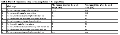
The rest of time the cars are moving or the observer is waiting for the rod car which is going to the next fore rod position.
Teams could measure 40 km a day if they only spend 40 sec per setup. During a work day, more than 500 setups could be measured. The productivity can be compared to Swedish motorized levelling. In the third precise levelling of Sweden, the daily average distance was about 13 km, which was measured in 5.5 hr (Vestøl et al., 2014). The average time per setup varied between 1.6 min and 2.4 min. The comparison shows that robotized levelling could be more productive.
In the example, it is assumed that measurements are performed directly from cars. In many cases this is not possible and connecting measurements are observed using a traditional levelling method. In the motorized method, extra rods are used for connecting measurements.
To take full advantage of robotized levelling, benchmark intervals should be longer than they are nowadays. Otherwise fast-moving measuring would be interrupted too often by connecting measurements. A suitable measuring time for a benchmark interval is about one hour. On flat roads the ideal distance for benchmark intervals would be more than 7 km. This is too sparse for local surveying purposes, so some kind of compromise is needed between productivity and local requirements.
Future outlook
At the moment we are heading towards a new era of robotized working environments, and hopefully someday robots and artificial intelligence solutions will help precise levelling work. Combining the robotized method with self-driving cars would create a fully automated measuring system. In any case, benchmark connections are needed, so robotized levelling would be based on cooperation between humans and robots. Robots could repeat work stages more accurately than humans, so it is a realistic scenario that in the future robotized levelling would be not only more productive more but also more precise.
References
Bélanger M., (2015). Collaborative robot. Ebook –Sixth edition. Robotiq. October 2015.
Cheves M. (2007). Fusing Measuring Innovation with Global R&D. American Surveyor, November 2007.
Feist, W., Glimm, A., Marold, T., Rosenkranz, H. (1996). Die Total Level Station DiNi®10T-Das erste digitale Nivelliertachymeter. VR 58/1. S.1-7.1996.
Hüther, G., (1973). The new automatic level Ni 002 of the Jena Optical Works. Jena Review. Jena, German Democratic Republic.
Ingesand, H. (1990). Das Wild NA 2000. Das erste digitale Nivellier der Welt. In: Allgemeine
Vermessungs Nachrichten 97 (1990), Seite 201 – 210. 1990.
Kim, S-B., J.-C. Bazin, H.-K. Lee, K.-H. Choi, S.-Y. Park. (2011). Ground vehicle navigation in harsh urban conditions by integrating inertial navigation system, global positioning system, odometer and vision data, IET radar, sonar & navigation 5.8 (2011): 814-823.
Murray, R. M., Li, Z., Sastry, S. S., and Sastry, S. S. (1994). A mathematical introduction to robotic manipulation. CRC press.
PCB Linear (2013). PCB Linear. Round Shaft Technology Catalog. A Pacific Bearing Company.(Accessed February 16, 2017, at www.pbclinear. com/Download/Catalog/Round- Shaft-Technology-Catalog.pdf)
Poetzschke, H. (1980). Motorized Leveling at the National Geodetic Survey. NOAA Technical Memorandum NOS NGS 26. Rockville, Md.
Schomaker, M. C., and R. M. Berry (1981). Geodetic Leveling. NOAA Manual NOS NGS 3. National Geodetic Survey. Rockville, Md.
Sokkia (2009). Sokkia SDL1X brochure. Topcon Corporation. (Accessed February 16, 2017, at www.totalsurvey.com.au/catalogues/ SDL1X_brochure%20600dpi%20.pdf)
Turek, F. D. (2011). Machine Vision Fundamentals: How to Make Robots ‘See’. NASA Tech Briefs, 35(6), 60-62, 2011.
Vestøl, O., Eriksson, P.-O., Jepsen, C., Keller, K., Mäkinen, J., Saaranen, V., Valsson, G., and Hoftuft, O. (2014). Review of current and near-future levelling technology – a study project within the NKG working group of Geoid and Height Systems. Lantmäterirapport 2014:2, Reports in Geodesy and Geographical Information System, Lantmäteriet, Gävle, 51 p., 2014.
Williamson M. (2015). Safe, Cheap, and Smart: Collaborative Robots in Manufacturing. Frontiers of Engineering: Reports on Leading-Edge Engineering from the 2014 Symposium (2015)
The paper was presented at FIG Working Week 2017, Helsinki, Finland, May 29–June 2, 2017.


 (No Ratings Yet)


Leave your response!