| Positioning | |
Positional accuracy enhancement of an INS/DGPS integrated system
|
||||
|
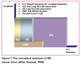
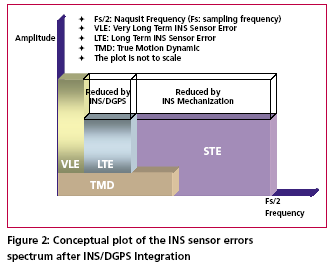
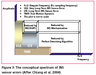
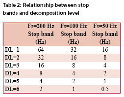
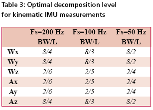
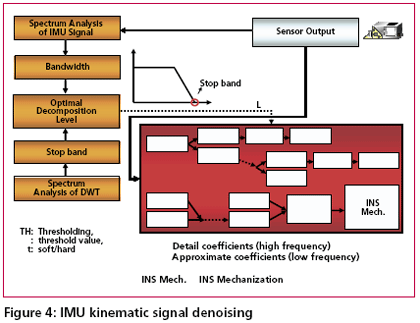
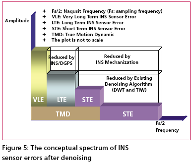
According to Skaloud [1999], the inertial sensor errors are composed of long term errors (low frequency components) and short term errors (high frequency components). Therefore, a conceptual plot of the frequency spectrum of the inertial sensor errors in the measurements can be illustrated as in Figure (1). Figure (2) shows how each of the errors is reduced by the INS/DGPS integration process. The long term errors are reduced by updating the filter with the observed error state vector coming from the GPS filter (position and velocity). Certain amounts of the short term errors are reduced by the smoothing that is done by the numerical integration process of the INS mechanization [Burton et al., 1999]. However, Figure (2) indicates the benefits of the INS/ DGPS integration are band-limited as the lower boundary of the error spectrum is mainly determined by remaining biases in the GPS observations while the upper boundary is mainly determined by short term inertial sensor errors.Consequently, the remaining GPS biases contained within the GPS navigation solution, such as ionospheric delay, tropospheric delay and multipath, are responsible for the very long term errors illustrated in Figures (1) and (2). Due to restrictions set forth by the sampling theory, the utilization of DGPS data to reduce the short term INS errors is not effective since the sampling rate of DGPS measurements (1Hz) is much lower than those of an inertial unit. As a result, the long term INS errors that are reduced by the integration process with GPS are usually more significant than the short term errors [Skaloud, 1999]. The long term errors usually include accelerometer biases and gyro drifts which are commonly modeled as error states. Therefore, the impact of these long term errors for long periods of time can be limited with external aiding. On the contrary, the remaining short term errors remain and contribute to the error accumulation during GPS signal outage periods. Consequently, Figure (3) illustrates that a perfect denoising algorithm is expected to preserve the true motion dynamic signal and remove unwanted short term errors completely. In addition, Figure (3) also implies that the key element of developing the pre-filtering algorithm for removing unwanted short term errors is to investigate the bandwidth of the true motion dynamics sensed by each inertial sensor individually. Thus, the objectives of this article are to: (1) identify the motion dynamic bandwidth of a typical land vehicle sensed by each inertial sensor individually, (2) evaluate the performance of the proposed algorithm using various INS/ DGPS integrated land vehicle systems, and (3) investigate the negative impacts of the cascade denoising algorithm on different INS/DGPS integrated land vehicle systems. Spectrum analysis of IMU kinematic signalshigh frequency (short term) error components of IMU signals. See Skaloud [1999], Burton et al., [1999], and Nassar [2004] for details. However, for land vehicle navigation applications the concern is in removing short term errors and improving the positioning accuracy during GPS signal blockages without jeopardizing the true motion dynamic components of the vehicle. Indeed, such operation requires the prior knowledge of the true bandwidth for typical land vehicle motion dynamics and the spectrum characteristics of the wavelet denoising algorithm. Thus, the positioning errors, after applying denoised kinematic IMU measurements, can be expected to be smaller than those obtained through the use of original data if the true motion dynamic content can be well preserved and the short term errors can be removed during the denoising operation. Chiang et al., [2004] investigated the bandwidth of true motion dynamics using kinematic IMU raw measurements sensed by several systems and suggested the bandwidth of true motion dynamics for general land vehicle applications as given in Table 1. See Chiang [2004] and Chiang et al., [2004] for more details about the spectrum analysis of kinematic IMU signals. The cause for the wider bandwidth sensed by the X-Gyro, YGyro YGyro and ZAccelerometer was mainly due to road irregularities (i.e., bumps). In contrast, the narrower bandwidth sensed by the XAccelerometer, YAccelerometer and Z-Gyro indicates a much smoother heading motion along the trajectory, which reflects the dynamic motion variation in typical land vehicle applications [Czonpo, 1990, Chiang et al., 2004 and Chiang 2004]. Traditional wavelet denoisingMallat [1989] proposed Multiresolution Analysis (MRA), which has been the most common and general approach to constructing a wavelet basis. In signal processing, such an idea is implemented as subband filtering, or quadrature mirror filtering [Strang and Nguyun, 1997]. The decomposition step consists of a low pass (h) and a high pass (g) filter followed by downsampling (? 2) (i.e., retaining only the even index samples), see Mallat [1999] for more details about wavelet decomposition. Chiang et al., [2004] investigated the relationship between the decomposition level, sampling frequencies (i.e., Fs=200Hz, Fs=100Hz, and Fs=50Hz), and the stop bands of residual frequencies corresponding to the approximate signals through the spectrum analysis of approximation signals (Ai,i=1, 2, 3…n) and the detail signals (Di,i=1, 2, 3…n) generated at each wavelet decomposition level, as indicated in Table 2. The relationship presented in Table 2 was derived using Daubechies wavelet functions (DB(i), i=2 First Generation Wavelet Denoising AlgorithmThe basic principle of the first generation denoising algorithm is to perform thresholding on the DWT of the noisy signal, and then take the inverse DWT of the thresholded coefficients to obtain the denoised signal. Donoho [1992] proposed the following schemes for denoising: 1) Suppose x(n) is the original signal of length n, y(n) = x(n) + e(n), where y(n) is corrupted by e(n) ~ N (0,1). Find the DWT of y(n) which is called Yj, k(n). 2) Perform proper thresholding on Yj, k(n) using d chosen based on Stein’s Unbiased Estimate of Risk or Threshold choice (SURE) (see Donoho [1992] for details) , see Chiang et al., [2004] for details about performance of different thresholding algorithms. 3) Take the inverse DWT of k j X , ˆ to Second Generation Wavelet Denoising AlgorithmThe DWT is not translation invariant (shift invariant), meaning that if a DWT is applied to a shifted version of a signal x, it cannot get the shifted version of the DWT of x [Lang et al, 1996]. The lack of translation invariance is not necessarily a problem for most applications, but for denoising this phenomenon introduces artifacts when using transform domain thresholding dependent on the kind of transform domain one is working in [Jansen, 2001]. For wavelet denoising the artifacts are related to the behavior near singularities. In the neighborhood of discontinuities, wavelet denoising can exhibit pseudo-Gibbs phenomena [Coifman and Donoho, 1995].To reduce the impact of pseudo-Gibbs phenomena, the Undecimated Wavelet Transform (UDWT), which has been independently discovered under several names, e.g., shift/translation invariant wavelet transform (TIW) [Coifman and Donoho, 1996], stationary wavelet transform (SWT) [Nason and Silverman,1995] or redundant wavelet transform, can be applied. Coifman and Donoho [1995] extensively studied the similar characteristics of the UDWT and implemented a so called Translation Invariant Wavelet Transform (TIW) based on the idea of Cycle-Spinning, or denoising all possible shifts of a signal and then averaging. The idea was originally explored to reduce the pseudo-Gibbs phenomena. If we let Sh represent the circular shift operator then for a signal X with length N, ShX(k) = X((k+h) mod N). Now if L represents the DWT operator, T represents the thresholding operator, Sh -1 and L-1 are the unshift and IDWT operators respectively, then the denoised signal is given by the following equation: The denoising procedure for IMU raw measurements is illustrated in Figure (4) where cAi (i = 1, 2, 3…n) and cDi (i = 1, 2, 3…n) are approximation and detail coefficients generated at each decomposition level. See Chiang [2004] for the relationship between approximation/detail signals and approximation/detail coefficients. The optimal decomposition level (L) varies with the bandwidth of true motion dynamics in each sensor. It can be chosen using Table 2 and the bandwidth of the true land vehicle motion dynamics listed in Table 1, which is given in Table 3. Chiang et al., [2004] indicated that the major limitation of applying either the 1st or 2nd generation denoising algorithms was the remaining high frequency components. The conceptual plot of the frequency spectrum of both the 1st and 2nd generation denoising algorithms is given in Figure (5). Therefore, the remaining issue involves removing the short term errors whose frequencies are higher than the stop band and reducing the short term errors whose frequencies are lower than the stop band when the existing wavelet denoising algorithm is applied to the IMU signals. |
||||
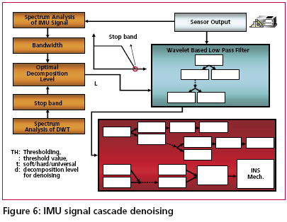
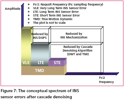
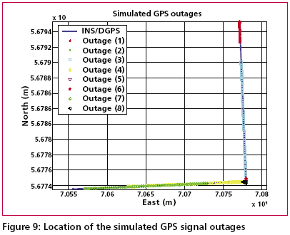
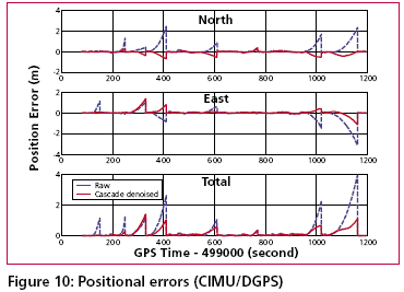
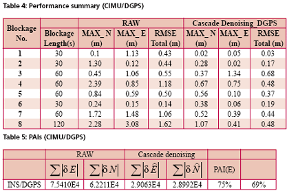
Development of the cascade denoising algorithmAs indicated previously, through a spectrum analysis of the DWT/TIW denoising algorithm and kinematic IMU signals, the bandwidth of the true motion dynamics sensed and the stop band of the wavelet-based low pass filter can be determined as given in Tables 1 and 2. As a result, an optimal decomposition level of the waveletbased low pass filter was determined. Since the signals whose frequency ranges are outside the bandwidth of the true motion dynamics are undesirable, wavelet-based low pass filters with optimal decomposition levels (L) can be applied for each sensor. These low pass filters are first used to remove undesirable high frequency components whose frequencies are higher than the stop bands and then applied to filter any remaining short term errors whose frequencies are lower than the stop bands of the low pass filters, as shown in the Figure (6). Through this spectrum analysis of the cascade denoising algorithm, the above mentioned limitations of the traditional denoising procedure can be removed. In addition, the cascade denoising is able to provide superior performance over traditional denoising algorithms in the position domain. The conceptual plot of the frequency spectrum of the cascade denoising algorithm is given in Figure (7). Comparing Figure (3) to Figure (5) and Figure (7), the spectrum of the cascade denoising resembles that of a perfect denoising algorithm. This implies that the cascade denoising is superior to traditional algorithms in the frequency domain. Furthermore, Chiang et al., [2004] showed that the cascade denoising is superior to traditional denoising algorithms in the position domain since it is capable of providing significant improvements in terms of the positioning accuracy during GPS outages. Results and discussionsTo asses the performance of the proposed cascade denoising algorithm a field test was conducted in October 2003 by the Mobile Multi-sensor Systems (MMSS) research Group of the University of Calgary. The test was conducted to replicate a typical land vehicle environment using three different INS/ DGPS integrated systems consisting of a navigation grade IMU (Honeywell CIMU), and two NovAtel OEM4 receivers. The performance of the cascade denoising algorithm was then evaluated in terms of the IMU qualities (i.e., accuracy levels). Figure (8) illustrates the test van and the set up of the IMU systems used in the test. The reference trajectory was generated using the CIMU/DGPS integrated system with a loosely coupled extended Kalman Filter integration scheme. There were no natural GPS signal outages in this test trajectory, and therefore, eight simulated GPS signal outages were simulated by removing the GPS solutions being fed into the INS Kalman filter during the integration process, see Figure (9) for the location of the simulated outages along the test trajectory. The navigation solutions obtained through the use of raw IMU measurements and denoised IMU measurements were then compared with the reference trajectory. Figure (10) and Table 4 provide summaries of the positional error performances when comparing the denoised INS/DGPS integrated navigation solutions to the raw INS/ DGPS integrated navigation solutions using a navigation grade IMU with the reference trajectory during each GPS signal outage period. It can be seen from Figure (10) that the cascade denoising algorithm was able to provide visible improvements during several GPS outage periods. As indicated in Table 4, the positional errors of six GPS outage periods were successfully reduced using denoised CIMU measurements. The rate of improvement for individual outage periods was 75% (6/8). In addition, the magnitude of improvement ranged from 20 centimeters to 1 meter and the percentage of improvement ranged from 20% to 90%. In contrast, the remaining two GPS outage periods were not significantly degraded by the denoising operation. The magnitude of this degradation ranged from 5 centimeters to 20 centimeters and the percentage of degradation ranged from 20% to 35%. To provide a more accurate description associated with the performance of the cascade denoising algorithm, a performance analysis index can be defined as Where TP is the total number of accumulated points during all GPS outages (t is the total length of all GPS outages and Fs is the sampling rate of the IMU), For navigation grade IMU (i.e., CIMU), the long term errors of the IMU (i.e., bias, drifts) are stable and well behaved. This means that the remaining short term errors of the IMU account for most of the residual position error during GPS signal outages. ConclusionsThis article presented a novel cascade denoising algorithm to reduce the impact of short term INS errors and improve the positioning accuracy during GPS signal blockages using several INS/DGPS integrated navigation systems. The key elements of any pre-filtering operation are to investigate the bandwidth of the true motion dynamics and remove the short term INS errors without deteriorating the true motion dynamic signal. The results of spectrum analyses demonstrated that the bandwidth of the true motion dynamics is very low. In fact, it can be divided into two groups. The first group consists of the XGyro, Y-Gyro, and Z-Accelerometer with corresponding bandwidth ranges from 0 to 6 Hz. In contrast, the second group is composed of XAccelerometer, Y-Accelerometer, and Z-Gyro corresponding to bandwidth ranges from 0 to 1Hz. In addition, the spectrum of the true motion dynamics is independent of the quality of the IMU used. The cascade denoising algorithm developed in this article was able to overcome the limitations of existing denoising algorithms in the frequency domain. In addition, it was capable of providing superior performance in the position domain. The results demonstrated that the cascade denoising algorithm provided the most significant improvement when using a navigation grade (CIMU-=[09) DGPS integrated system; the percentage of improvement reached 58%. For a navigation grade IMU (e.g., CIMU) the long term errors (e.g., bias, drifts) were stable and well behaved, while the remaining short term errors dominated. AcknowledgementsThis study was supported in part by research fund from National Science Council of Taiwan (NSC 95-2221-E- 006 -335 -MY2), the Natural Science and Engineering Research Council of Canada (NSERC) and the Canadian Geomatics for Informed Decisions (GEOIDE) Network Centers of Excellence (NCE). Dr. Eun-Hwan Shin is acknowledged as a co-author of the AINS® toolbox used in the article for providing the INS mechanization and INS/GPS extended Kalman filter. ReferencesBruton, A.M., Skaloud, J., Schwarz, K.P. (1999): The Use of Wavelets for the Analysis and De-noising of Kinematic Geodetic Measurements. Geodesy Beyond 2000- IAG General Assembly, Birmingham, UK, July 19-24, International Association of Geodesy Symposia, Vol. 121, 2000, Springer, 227-232. Chiang, K.W., Hu, H., El-Sheimy, N., and Niu, X. (2004): Improving Positioning Accuracy of a GPS/ MEMS Integrated Vehicular Navigation System During DGPS Outages Periods Utilizing Cascade Denoising Algorithm, GNSS 2004, ION, September 21-24, 2004 – Long Beach, California, USA Chiang, K.W. (2004): INS/GPS Integration using Neural Networks for Land Vehicular Navigation Application, PhD thesis, Department of Geomatics Engineering, The University of Calgary, UCGE Reports 20209 Czompo, T. (1990): Use of Spectral Methods in Strapdown ISS Data processing, Proceedings of the international Symposium on Kinematic System for Geodesy, Navigation and remote sensing, Banff, September 10-14,Springer-Verlag,New York. Coifman, R.R. and Donoho, D.L. (1995): Translation-Invariant De-Noising, Lecture Notes in Statistics, 103,pp.125-150,Yale University and Yale University Daubechies, I. (1992): Ten Lectures on Wavelets. Philadelphia:SIAM. Donoho, D.L. (1992): De-Noising via Soft Thresholding. IEEE Trans. Info. Theory, Vol.41,No.3, May 1995,pp.613-627 Jansen, M. (2001): Noise reduction by wavelet thresholding, New York Springer, Lang M., Guo, H., Odegard, J.E., and Burrus, C. S., and Wells Jr. R. O. (1996): Noise Reduction Using an Undecimated Discrete Wavelet Transform. IEEE Signal Processing Letters, 3(1):10-12, Jan. 1996. Mallat, S. (1989):A Theory of Multiresolution Signal Decomposition: The Wavelet Representation, IEEE Trans.PAMI,11,pp674-693 Mallat, S. (1999): A Wavelet Tour of Signal Processing, Academic Press, 2nd edition, 1999 Nason, G., and Silverman, B.(1995): The stationary wavelet transform and some statistical applications, in Wavelets and Statistics (Antoniadis and Oppenheim eds.), P.281-299 Nasser, S.(2004):Improving the Inertial Navigation System (INS) Error Model for INS and INS/DGPS Applications. PhD thesis UCGE Reports 20183, Department of Geomatics Engineering, The University of Calgary Skaloud, J. (1999):Optimizing Georeferencing of Airborne Survey Systems by INS/DGPS, PhD thesis, Department of Geomatics Engineering, The University of Calgary Strang, G., and Nguyen, T. (1997): Wavelets and Filter Banks. Wellesley-Cambridge Press. |
||||||||||||||||||||||||||||||||||||||||
|
||||||||||||||||||||||||||||||||||||||||
|
Pages: 1 2






 (No Ratings Yet)


