| Navigation | |
Operation and implementation of heading reference system
DATA FUSION
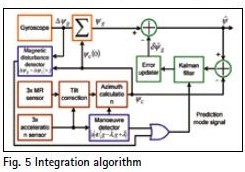
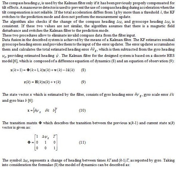
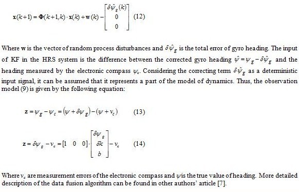
The Heading Reference System uses the gyroscope data and the compass data to determine current heading [4, 5, 6]. The design utilizes a Kalman filter (KF) [6] to integrate the measurement data and estimate gyroscope errors. The results of estimation are subsequently used to calculate the estimated heading . The block diagram of the implemented integration algorithm is shown in Fig. 5.
HRS HARDWARE IMPLEMENTATION
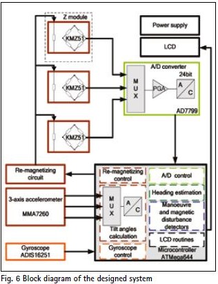
During the research work, a hardware implementation of the described Heading Reference System has been developed. The main task of the system is to determine the current heading on the almost continuous basis and with possibly high accuracy. It was assumed that the system should consist of low cost elements, have small dimensions, and battery supply. The block diagram of the prototype is shown in Fig. 6.
The HRS is controlled by an Atmel AVR microcontroller which performs initialization, measurement and calibration routines and executes integration algorithm.
Magnetoresistive sensors were used for magnetic field measurements. Tilt compensation procedure uses data from 3-axis MEMS accelerometer. Included gyroscope sensor is a fully autonomous device. It is able to measure angular rate and determine angle change.
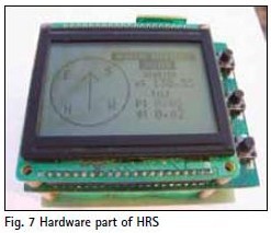
The estimated heading is displayed on a graphical LCD module with additional information such as pitch and roll angles, current mode of filter operation (only prediction or normal work) and information about detected magnetic field disturbances and manoeuvres. Fig. 7 shows the hardware of the designed Heading Reference System.
HRS EVALUATION AND CONCLUSIONS
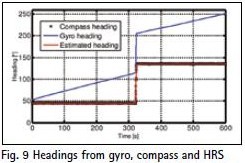
Simple statistics for the stationary period of time for the second testing scenario (Fig. 9) have been shown in Table 1.
Table 1 Statistics of heading errors
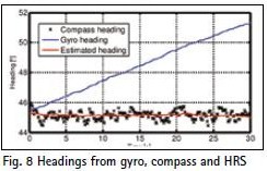
As can be seen in Figs. 8-9, the gyro heading tends to almost linearly increase because of cumulative gyro errors. The compass heading has long term stability, but it is noisy. The implemented integration algorithm enables estimation of heading, taking into account short term gyro accuracy and long term compass stability. As a result fast response of the system has been preserved and noise of the compass heading have been significantly reduced.
REFERENCES
1. Caruso M.J.: Applications of Magnetic Sensors for Low Cost Compass Systems, PLANS 2000, pp. 177-184, 2000.
2. Electronic Compass Design using KMZ51 and KMZ52, Application Note AN00022, Philips Semiconductors, 2000.
3. Electronic Tilt Compensation, Application Note AN-00MM-004, Memsic, 2008.
4. Ladetto Q., Gabaglio V., Merminod B.: Combining Gyroscopes, Magnetic Compass and GPS for Pedestrian Navigation, KIS, Banff, Canada, pp. 205-212, 2001.
5. Stephen J., Lachapelle G., Development and Testing of a GPS-Augmented Multi-Sensor Vehicle Navigation System, Journal of Navigation, Vol. 54, No. 2, pp. 297-319, 2001
6. Farrell J.A.: Aided Navigation GPS with High Rate Sensors, McGraw-Hill, USA, 2008.
7. Kaniewski P., Kazubek J.: Acta Physica Polonica A „Integrated System for Heading Determination” Vol. 116, No.3, s. 325-330, ISSN 0587-4246
My Coordinates |
EDITORIAL |
|
His Coordinates |
Vice Admiral B R Rao |
|
Mark your calendar |
MARCH 2011 TO AUGUST 2011 |
|
News |
INDUSTRY | LBS | GPS | GIS | REMOTE SENSING | GALILEO UPDATE |
Pages: 1 2



 (3 votes, average: 3.67 out of 5)



Leave your response!