| Navigation | |
Operation and implementation of heading reference system
A brief outline of the three segments – User Segment, Space Segment and Ground Segment necessary for implementation of an SBAS system over the Indian airspace |
|
 |
|
||||
 |
|
||||
Whenever there is a need for continuous navigation, radio-technical systems are usually integrated with inertial navigation systems (INS) or dead-reckoning systems (DR). Due to large dimensions and power consumption, as well as high prices, INS systems have been traditionally applied in high-end or military applications. Recently an unprecedented decrease of all the above mentioned factors have been witnessed, making inertial navigation suitable for a wider set of applications. However, the dead-reckoning method is still the preferred choice in low-cost land navigation systems.
Dead Reckoning (DR) allows to determine the current position of a vehicle using heading and velocity measurements. One of the data streams needed for DR can be provided by the Heading Reference System (HRS). The HRS provides heading estimates, which allow DR to calculate the direction of a vehicle displacement and, along with velocity information, to predict the current position of the vehicle.
This article presents a project and hardware design of HRS system, utilizing an electronic compass with tilt sensors and a gyro. These additional sensors are used to correct the compass measurements. The main task of the developed system is to determine the current heading on the almost continuous basis and with as high accuracy as possible.
MAGNETIC AZIMUTH
The main subsystem of the designed HRS is an electronic compass module. It allows heading estimation, based on the Earth’s magnetic field measurements.
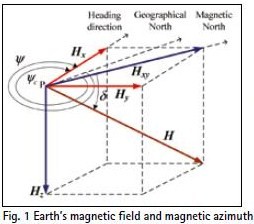
To determine the magnetic heading, the components of Earth’s magnetic field have to be measured in two orthogonal, parallel to the Earth’s surface, directions. The three dimensional Earth’s magnetic field vector and its relationship with the magnetic azimuth is shown in Fig. 1 [1, 2].
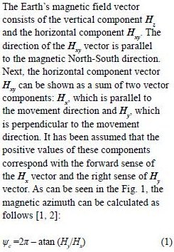
As can be seen in the equation (1), it is sufficient to measure only two horizontal components of the Earth’s magnetic field to calculate the magnetic azimuth. One should take into consideration that it is crucial to measure the horizontal components. That is the reason why the magnetic sensors in the compass module should be gimballed mechanically or electronically.
ELECTRONIC GIMBALLING
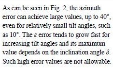
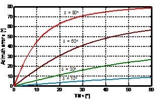
When the compass module is tilted, the measured components do not equal horizontal components of the Earth’s magnetic field [5, 6]. Because of that, the angle determined with the use of the equation (1) is sensitive to the tilt of the compass. The influence of the tilt angle τ and the inclination angle δ (see Fig. 1) on the azimuth error are shown in Fig. 2.
Fig. 2 Influence of tilt and inclination on azimuth
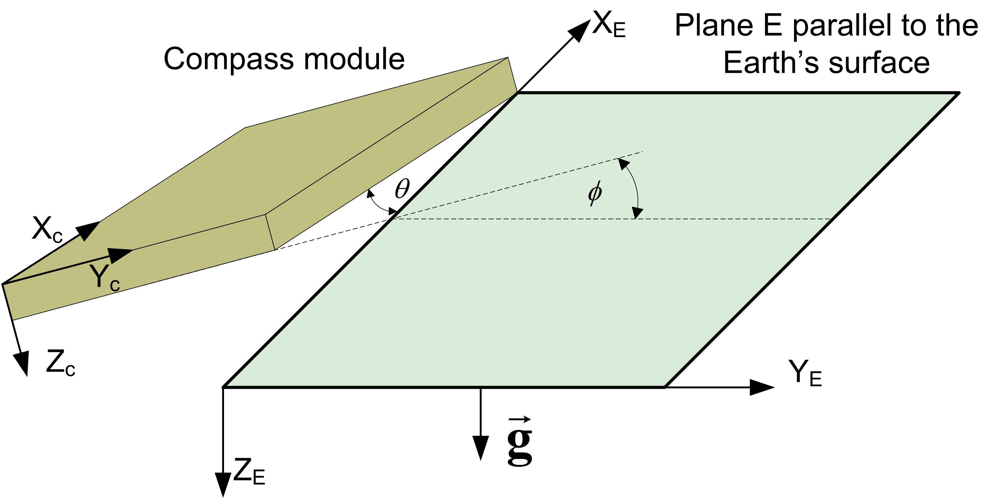
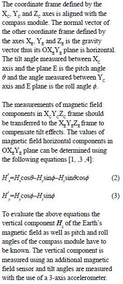
Electronic tilt compensation has been applied to reduce compass tilt errors in the designed HRS. Fig. 3 shows pitch and roll angles of the electronic compass module [2, 4].
Fig. 3 Compass module orientation
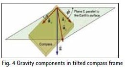
Fig. 4 Gravity components in tilted compass frame
GYROSCOPE CORRECTION
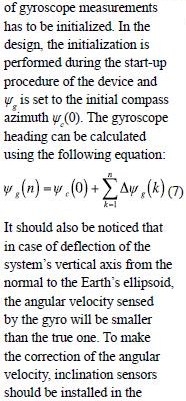
system [5]. There is also another simple method of correction, which assumes that the overall effect of deflections can be compensated by multiplying angular velocity measurements from gyro by a constant coefficient, greater than one [5].
–~~~~~~~~~~~~–
DATA FUSION
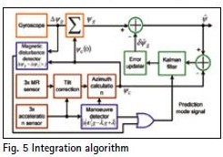
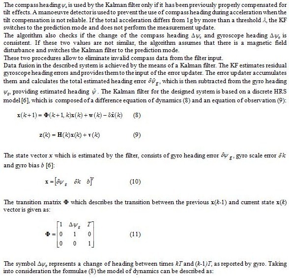
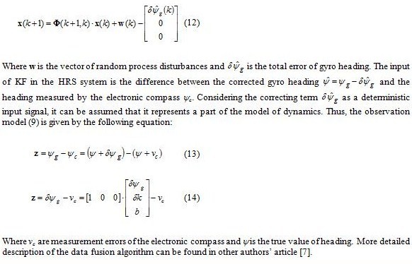
The Heading Reference System uses the gyroscope data and the compass data to determine current heading [4, 5, 6]. The design utilizes a Kalman filter (KF) [6] to integrate the measurement data and estimate gyroscope errors. The results of estimation are subsequently used to calculate the estimated heading . The block diagram of the implemented integration algorithm is shown in Fig. 5.
HRS HARDWARE IMPLEMENTATION
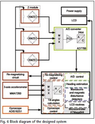
During the research work, a hardware implementation of the described Heading Reference System has been developed. The main task of the system is to determine the current heading on the almost continuous basis and with possibly high accuracy. It was assumed that the system should consist of low cost elements, have small dimensions, and battery supply. The block diagram of the prototype is shown in Fig. 6.
The HRS is controlled by an Atmel AVR microcontroller which performs initialization, measurement and calibration routines and executes integration algorithm.
Magnetoresistive sensors were used for magnetic field measurements. Tilt compensation procedure uses data from 3-axis MEMS accelerometer. Included gyroscope sensor is a fully autonomous device. It is able to measure angular rate and determine angle change.
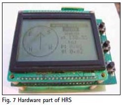
The estimated heading is displayed on a graphical LCD module with additional information such as pitch and roll angles, current mode of filter operation (only prediction or normal work) and information about detected magnetic field disturbances and manoeuvres. Fig. 7 shows the hardware of the designed Heading Reference System.
HRS EVALUATION AND CONCLUSIONS
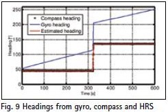
Simple statistics for the stationary period of time for the second testing scenario (Fig. 9) have been shown in Table 1.
Table 1 Statistics of heading errors
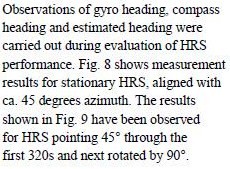
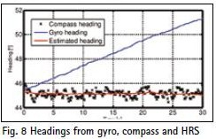
As can be seen in Figs. 8-9, the gyro heading tends to almost linearly increase because of cumulative gyro errors. The compass heading has long term stability, but it is noisy. The implemented integration algorithm enables estimation of heading, taking into account short term gyro accuracy and long term compass stability. As a result fast response of the system has been preserved and noise of the compass heading have been significantly reduced.
REFERENCES
1. Caruso M.J.: Applications of Magnetic Sensors for Low Cost Compass Systems, PLANS 2000, pp. 177-184, 2000.
2. Electronic Compass Design using KMZ51 and KMZ52, Application Note AN00022, Philips Semiconductors, 2000.
3. Electronic Tilt Compensation, Application Note AN-00MM-004, Memsic, 2008.
4. Ladetto Q., Gabaglio V., Merminod B.: Combining Gyroscopes, Magnetic Compass and GPS for Pedestrian Navigation, KIS, Banff, Canada, pp. 205-212, 2001.
5. Stephen J., Lachapelle G., Development and Testing of a GPS-Augmented Multi-Sensor Vehicle Navigation System, Journal of Navigation, Vol. 54, No. 2, pp. 297-319, 2001
6. Farrell J.A.: Aided Navigation GPS with High Rate Sensors, McGraw-Hill, USA, 2008.
7. Kaniewski P., Kazubek J.: Acta Physica Polonica A „Integrated System for Heading Determination” Vol. 116, No.3, s. 325-330, ISSN 0587-4246
My Coordinates |
EDITORIAL |
|
His Coordinates |
Vice Admiral B R Rao |
|
Mark your calendar |
MARCH 2011 TO AUGUST 2011 |
|
News |
INDUSTRY | LBS | GPS | GIS | REMOTE SENSING | GALILEO UPDATE |
Pages: 1 2




 (3 votes, average: 3.67 out of 5)


Leave your response!