| Positioning | |
Multi-GNSS positioning campaign in South-East Asia
In this study, the preliminary results of multi-GNSS software receiver to highlight the availability, the quality and the potential of the multi-GNSS positioning environment are summarized |
 |
|
 |
|
 |
|
 |
|
 |
|
 |
|
Over the past three decades the only two available Global Navigation Satellite Systems (GNSS) have been the American GPS and the Russian GLONASS. Although these systems have been initially developed for military applications, while time has been passing, the interest in using these facilities also for deriving position, velocity and time (PVT) in civilian applications has registered a continuously growing interest. As a consequence in few decades we have reached the point in which GNSSes have a key relevance in almost any sector of modern society. Efficient solutions and innovative infrastructures are increasingly using this enabling technology to ensure safer and better services in almost any branch of modern life from transportation systems (air, road, rail sea) to disaster management, from agriculture to environment monitoring, natural resources exploitation, infrastructure management, safety, and much more.
However for long time the first two available GNSSes have been mainly regarded as alternative options so that receivers, application and services have been developed for one of them only.
When at the end of the twentieth century the design of new GNSSes started together with some Regional Navigation Satellite Systems (RNSS) [1] the scientific community and commercial users have started to consider benefits and challenges of a multi-GNSS environment analysing the possibility to use jointly two or more systems and debating problems and difficulties that could arise by such an environment [2][3][4].
Recently, the multi-GNSS environment has become reality due to the completely recovered global constellation of GLONASS, the launches of the new 4 In-Orbit-Validation (IOV) satellites of Galileo, and the start of the civil service for Asia-Pacific region of Beidou. This paper presents the work in development of multi-GNSS positioning solutions, with focuses on signal processing algorithms, able to accommodate multiple systems, in all blocks of the receiver.
The solutions are tested with real data collected from all 4 GNSSes to analyse the advantages of multi-GNSS environment for civil users worldwide.
Multi-GNSS environment
Status of all GNSSes
In this section a short overview of the status of the different analyzed GNSSes is presented for reference.
GPS: As remarked GPS is the first GNSS and it has been continuously working for decades. The system has undergone maintenance and has been modernized with the launch of new types of satellites equipped with new capabilities. As designed, the full constellation has 24 medium elevation orbits (MEO) satellites on six orbit planes, which have approximately 55° inclination relative to the equator and are separated by 60° right ascension of the ascending node [5].
GLONASS: is the GNSS developed by the Soviet Union in the past and Russia currently. Its constellation is composed of 24 MEO satellites on three orbital planes (8 satellites evenly spaced on each orbit). In 2011, the full constellation of GLONASS was restored. Unlike the other GNSSes, GLONASS broadcasts FDMA signals; however in future with new satellite generations, GLONASS will broadcast CDMA signals also [8].
Galileo: The European GNSS foresees 27 MEO working satellites on 3 orbital planes, which have 56° inclination relative to the equator and are separated by 120° right ascension of the ascending node. Currently the Galileo system is under deployment and only its first 4 satellites were launched. These satellites have been transmitting the open service signal since March 2013 thus enabling the Galileo-only position fix [6]. New satellites should be launched over the next few years to allow the system to become fully operational [7].
Beidou: This Chinese GNSS foresees the use of 3 different types of satellites: (i) geosynchronous equatorial orbit (GEO); (ii) inclined geosynchronous orbit (IGSO) with an inclination angle to the equatorial plane of 55°; and (iii) MEO. At present the Beidou system consists of 14 satellites (5 GEO, 5 IGSO and 4 MEO satellites). The existing satellites started offering services to users in the Asia- Pacific region in December 2012 [9].
The signal spectrum of each GNSS is shown on Figure 1.

Advantages of Multi- GNSS environment
Availability increase: Obstacles like high buildings, trees… in urban canyons prevent a receiver from receiving signals from at least 4 satellites of a GNSS system for positioning purposes. However, if the receiver can work with other GNSSes (i.e. more navigation satellites), the problem of lacking satellites is solved. This is the scenario in which the multi-GNSS environment shows its most importance.
Accuracy improvement: Multi- GNSS environment is significant for not only availability but also accuracy improvements. Research in [10] showed that GPS stand-alone gives users worldwide a mean horizontal positioning accuracy (over 95% of time) of about 30 meters, while that of the combined GPS and Galileo positioning is less than 5 meters.
Reliability increase: Intentional and un-intentional interference sources, including jammers and spoofers, are major threats for GNSS services. The redundancy provided by multi-systems and multi-frequency bands are really important to increase the robustness of GNSS receivers, as well as the reliability of the positioning services.
Challenges of Multi- GNSS environments
Inter-system interference: GNSSes broadcast navigation signals in overlapped frequency bands. This fact could be convenient from the viewpoint of receiver design, but on the other hand, raises the issues of inter-system interference. However, as for GPS and Galileo, the signals were designed in the ways that reduce that interference while support interoperability [7].
Complexity increase: the new and upgraded GNSSes broadcast modern signals, which have advanced but complex structures in multiple frequency bands. These signals give much improvement in terms of accuracy, availability, and reliability to navigation services, but also challenge receivers to accommodate for such advantages. In multi-GNSS solutions, the analog parts of a receiver must operate with multiple systems, multiple frequency bands at larger signal bandwidths. These requirements surely increase the complexity and consequently the cost of the receiver. As for the digital parts, the signal processing requires more advanced and complex algorithms to cope with multiple systems, multiple channels as well as to fully exploit the advantages of the modern signals. These increase the computational complexity, the resource capability requirements and eventually the cost of the receiver. Recently, together with the rapid improvement in computational capability of programmable processors, such as CPU, GPU, DSP, and FGPA… the software receiver approach, which minimizes the hardware requirements, is favourable for the multi-GNSS solution because of its flexibility, easy-to-upgrade for complex requirements.
However, the important advantages of multi- GNSS environment together with the development in the electronic industry give a promising future for multi-GNSS solution.
Table 1. Characteristics of the civil signals in the campaign

Multi-GNSS positioning solution
Figure 2 shows the signal processing chain of a conventional GNSS receiver.

The chain consists of 5 main blocks, namely: (i) frontend; (ii) signal synchronization composed of acquisition and tracking processes; (iii) data demodulation; (iv) Position Velocity and Timing computation; and (v) display and storage. In the following sub-sections, each block is introduced together with our solutions for multi-GNSS positioning. It should be noted that in this campaign, the civil signals broadcasted by all 4 GNSSes are considered (see Table 1). These signals are referred hereafter by their abbreviation, L1-C/A (GPS), E1 (Galileo), B1 (Beidou), and L1-OF (GLONASS).
Antenna and front-end
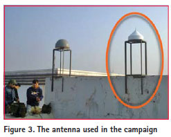
For the purpose of multi-GNSS positioning with free civil signals, the chosen antenna must be capable of receiving the signals in Table 1. In the campaign, the antenna AeroAntenna Choke Ring AT1675-120 with a frequency band of [1525 ÷ 1615] MHz is used.
The radio frequency (RF) signal from the antenna goes through the front-end, which is responsible for conditioning and converting the analog RF signals to the digital IF samples.
In this campaign, the MAX2769 frontend [11] is chosen. The configuration of the front-end is reported in Table 2.

It should be noted that the chosen bandwidth of the L1-OF signal is larger (8 MHz) since the GLONASS uses FDMA as the multiple access method for this signal.
Signal synchronization
The general representation of a digital GNSS signal after the front-end is showed on (1).
![]()
where C is the carrier power (W); c[n] is the spreading code of the navigation signal; for the CDMA signals, i is the PRN number uniquely assigned for a satellite, however for the GLONASS FDMA signal, i is common for all satellite; FIF, fd denote the Intermediate Frequency (IF) and Doppler shift (Hz) respectively; k = 0 for the CDMA signals, but for the FDMA signal, k is uniquely assigned for a satellite in view; TS = 1/FS stands for the sampling period (s) (FS is the sampling frequency (Hz)); φ is the initial carrier phase (rad); θ is the initial code delay (samples); and nW is the Additive White Gaussian Noise (AWGN) with zero mean (μ = 0) and variance σn 2 (nW ~ N (0, σn 2)). It should be noted that PRN codes are used not only for the multiple access purpose, but also for the ranging purpose to measure the distance between the receiver and the satellites in view. Table 1 also summarizes the characteristics of the PRN codes of each system. The main task of the signal synchronization block is to create a local replica of r[n], referred to as r[n], for code and carrier wipe-off. This block is usually divided into signal acquisition and tracking processes.
Signal acquisition process
The main objectives of this process are: (1) to determine the satellites in view (i for the CDMA signals, and k for the FDMA signal); (2) to roughly estimate the incoming signal parameters namely:
![]()
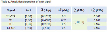
In fact, the acquisition is a search process; which generates tentative local replica signals made of![]() and tries to find the one closest to the received signal. For each tentative replica, the estimation is performed via calculating the correlation also referred as the Cross Ambiguity Function (CAF) between the received signal and the local replica over a dwell time T, which is often equivalent to one full PRN code length (see Table 1). The correlation value is compared with a pre-determined threshold to decide which hypothesis between H0 (unmatched), H1 (matched) is true [12]. The uncertainty of the three parameters creates a 3-D search space for each signal as reported in Table 3. Note that: in Table 3, for code phase search, the uncertainty is one full code, with the conventional step size of 0.5 chip (0.25 chip for E1 due to BOC(1,1) modulation of the signal [7]); and for the Doppler search, the uncertainty is for a general moving receiver, with the conventional step size being:
and tries to find the one closest to the received signal. For each tentative replica, the estimation is performed via calculating the correlation also referred as the Cross Ambiguity Function (CAF) between the received signal and the local replica over a dwell time T, which is often equivalent to one full PRN code length (see Table 1). The correlation value is compared with a pre-determined threshold to decide which hypothesis between H0 (unmatched), H1 (matched) is true [12]. The uncertainty of the three parameters creates a 3-D search space for each signal as reported in Table 3. Note that: in Table 3, for code phase search, the uncertainty is one full code, with the conventional step size of 0.5 chip (0.25 chip for E1 due to BOC(1,1) modulation of the signal [7]); and for the Doppler search, the uncertainty is for a general moving receiver, with the conventional step size being: ![]() .
.
Signal tracking process
Except the satellite id, the signal parameters estimated by the acquisition process are not accurate enough to be used for positioning and navigation. Moreover, these parameters change over time due to the Doppler effects on code and carrier. Therefore, to completely remove the code and carrier from the received signal, the synchronization block needs another process, so-called tracking, in order to produce the fine estimates of the signal parameters as well as to dynamically follow their variations. A standard tracking process consists of two concatenated loops, which are code tracking and carrier tracking. The two loops are strictly interrelated, and work in a concatenated way [13].
The chosen code tracking loop is a noncoherent “normalized early minute late power” Delay Lock Loop (DLL). The input signal is split into two paths and correlated with two versions, an early and a late of the local PRN code. The two versions are equally spaced (0.5 chip for L1-C/A, B1, L1-OF, and 0.25 chip for E1 due to BOC(1,1) modulation [13]) about the prompt PRN code. Based on the early and late correlation values, the “normalized early minute late power” discrimination function is formed to tune the code phase estimate perfectly matching with the received one.
For all the signals, the Costas loop, which is insensitive to the phase transitions due to navigation data bits, is chosen for the carrier tracking. The discrimination function is the phase error: ![]() with Ik, Qk being the energy in the in-phase and quadrature branches at time instance k respectively. The phase error is used to tune the Numerically Controlled Oscillator (NCO) to produce the local carrier perfectly matching with the received one [13].
with Ik, Qk being the energy in the in-phase and quadrature branches at time instance k respectively. The phase error is used to tune the Numerically Controlled Oscillator (NCO) to produce the local carrier perfectly matching with the received one [13].
Data demodulation module
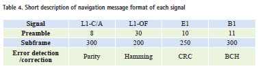
After the signal synchronization block, the code and the carrier are completely removed from the received signal. Based on the encoding scheme and the message format of each signal, the data demodulation block recovers the navigation message. The navigation message includes (i) ephemeris and (ii) almanac data. The content of the navigation message is also validated in this module based on the error detection and correction mechanism of the signal, see Table 4.
PVT computation block
The block is responsible for computing the position, the velocity and also the time of an object attached with the receiver. To do so, the block performs:
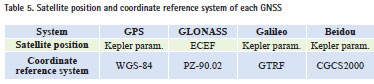
– Satellite position calculation based on the navigation messages: whereas GPS, Galileo and Beidou use Kepler parameters to identify the position of the satellites, GLONASS provides directly the coordinates of the satellites in the Earth-Centered, Earth- Fixed (ECEF) coordinate system;
– Pseudo-range estimation: the ranges between the receiver and the satellites are measured via the signal travel time based on the information from the navigation messages and the synchronization block. However, the error sources such as: satellite clocks, ephemeris errors, noise, atmospheric delays… make the measured ranges being just the pseudo ones.
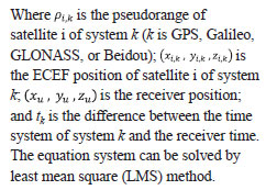
– Navigation equation system solving: in principles, GNSS uses tri-lateration technique to compute the position (x,y,z) of an object. By measuring the ranges from the object to three satellites at known position in the sky, the 3-equation system is obtained. Solving this equation system gives the position of the object. The obtained ranges are measured by the travel time, however, although the satellite clocks are synchronized to the standard time system, but the receiver clock is not. Therefore, an extra unknown, the bias of the receiver clock to the time system, is added. This unknown requires one more satellite to make the equation system with 4 unknowns solvable. In multi-GNSS solution, among the systems, there is no common time system. Without loss of generality, let us assume that GPS time is the standard time, adding one more system to the positioning solution means adding one more unknown, which accounts for the difference between the time of that system and the GPS time, to the navigation equation system. For example, if all 4 GNSSes are considered, the navigation equation has 7 unknowns. The equation is show on (2).
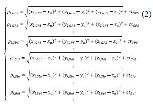
However, Galileo also broadcasts in its navigation message the so-called “GPS to Galileo System Time Conversion and Parameters”. By using these parameters, the extra unknown is not necessary. However, to make a general solution for all the systems, these parameters are not used in this work.
Furthermore, each GNSS uses its own coordinate reference systems as reported in Table 5, these differences contribute to positioning errors at level of some centimetres [13].
Results and analyses
The experimental results described in this part are obtained by using real datasets collected through the Aero Antenna Choke Ring AT1675- 120 on the roof of the NAVIS Centre building (Figure 3)
Standalone positioning result
Since the other signals show the similar behaviours, Figure 3 shows only the results of the signal synchronization block in case of the L1-C/A signal broadcasted by the PRN 5. As seen in Figure 3(a), the correlation peak is clearly emerged from the noise floor. This peak gives the satellite id (PRN 5), and the rough estimates of the code phase (3181 samples) and Doppler shift (1600 Hz) of the received signal. As for the tracking results, the upper plot of Figure 3(b) shows that the carrier tracking loop locks to the true carrier with a noise of 20 Hz. The result in the lower plot clearly shows that the DLL also locks to the true code phase. The prompt correlation values are the highest; meanwhile the early and late values are similar.
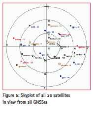
The signal synchronization, data demodulation and the PVT computation blocks give the identification and also the position of all 26 satellites in view from all GNSSes as seen in Figure 4.
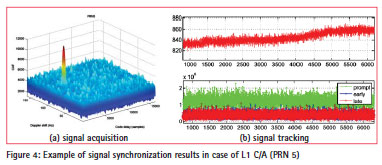
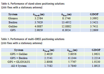
Table 6 shows the accuracy of the positioning results of each system obtained from the datasets of the campaign. It should be noted that the results should not be generalized to make the performance comparison among GNSSes, which can only be done with exhaustive investigations in well-designed scenarios, and especially when all systems fully operate.
The three performance parameters are the location easting and northing errors (i.e. standard deviation), and the Geometric Dilution of Precision (GDOP) parameter. When visible navigation satellites are close together in the sky, the geometry is said to be weak and the GDOP value is high; when far apart, the geometry is strong and the GDOP value is low. As seen in Table 6, GPS has the highest positioning accuracy related to its GDOP being smallest. The skyplot in Figure 5. shows the strong geometry of GPS. Meanwhile, Galileo shows its poor performance since at that moment there are only 4 Galileo satellites, just enough for positioning. Considering Beidou, its northing error is highest, since in Figure 5, its satellites are close together and 4 of them are geostationary satellites at the equatorial plane. GLONASS gives a good accuracy since currently it is one of the two complete systems.
Multi-GNSS positioning results
In this subsection, the multi-GNSS positioning solutions in different scenarios are considered. Since currently GPS is the most popular and also dominant navigation system for civil purposes, the combination between GPS and each other system is investigated. As seen in Table 7, the multi-GNSS solutions always give better results than stand-alone solutions, which were already reported in Table 6. This is due to the fact that more satellites give more information and better geometry.
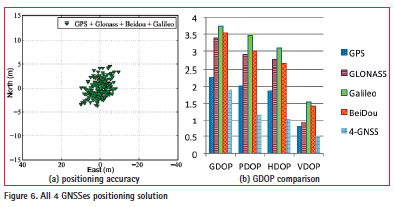
The last scenario is to consider all 4 systems for a common positioning solution, as reported in Table 7 and in Figure 6(a) the accuracy of this solution is the best in comparison with the others. Figure 6(b) shows the improvement of GDOP in this solution with respect to the stand-alone ones.
Conclusion
This paper has presented the positioning results of the existing and also the recently launched Global Navigation Satellites Systems including GPS, GLONASS, Galileo and Beidou. More importantly, the paper has proved that the multi-GNSS positioning in the South East Asia region is possible and its performance is outperform the stand-alone ones in terms of positioning accuracy, availability and reliability.
Future works will focus on exhaustive investigations of multi-GNSS positioning towards an objective of proposing suitable system combinations in different scenarios.
Acknowledgement
This work has been partially supported by the G-NAVIS project (FP7-GALILEO-2011- GSA-1-a, G.A. no 287203) References
1. Takahashi, H. “Japanese Regional Navigation Satellite System “The JRANS Concept”, Journal of Global Positioning Systems 3.1-2 (2004): 259-264.
2. Rizos, Chris. “Multiconstellation GNSS/RNSS from the perspective of high accuracy users in Australia” Journal of Spatial Science 53.2 (2008): 29-63.
3. T. H. Ta, S.Qaisar, A. Dempster, F. Dovis, “Partial Differential Post Correlation Processing for GPS L2C Signal Acquisition”, IEEE Transactions on Aerospace and Electronic System, vol. 48
4. T. H. Ta, F. Dovis, D. Margaria, and L. L. Presti, “Comparative Study on Joint Data/ Pilot Strategies for High Sensitivity Galileo E1 Open Service Signal Acquisition”, IET (previously IEE) Radar.
5. Navstar GPS Interface Specification IS-GPS-200 revision F. Technical report, Navstar GPS Joint Program Office, Sep 2011
6. Tung Hai Ta, Gustavo Belforte, “Four Galileo Birds Sighted over Asia”, GPSWorld Newsletter, April 9th 2013.
7. European Union, European GNSS (Galileo) Open Service Signal In Space ICD, issue 1.1, Sep 2010
8. Global Satellite Navigation GLONASS. “Interface Control Document”. Navigational radiosignal In bands L1, L2 (Edition 5.1), Moscow, 2008.
9. China Satellite Navigation Office. “Beidou Navigation Satellite System Signal In Space Interface Control Document”, Open Service Signal B1I (Version 1.0). Dec 2012.
10. “Service of Coordinated Operational Emergency & Rescue using Egnos – SCORE Project”: website: http:// www.shega.eu/score/score.html
11. MAXIM IntegratedTM, MAX2769 Datasheet, 2007.
12. F. Dovis, T. H. Ta, “Chapter 1: High Sensitivity Techniques for GNSS Signal Acquisition”, Global Navigation Sateliite System: Signal, Theory and Applications, Prof. Shuaggen Jin
13. Elliott D. Kaplan, editor. “Understanding GPS: Principles and Application”, Artech House, 2nd edition, November 2005


 (7 votes, average: 2.86 out of 5)


Leave your response!