| GNSS | |
Monitoring of the interference environment on large vehicles
In this paper we propose a jamming and spoofing detection test system comprising one or two jamming detectors and a network of record and replay systems, triggered centrally by a high precision timing unit, plus a time and frequency monitoring card. The monitoring card detects time jumps and thus spoofing. |
 |
|
 |
|
In traffic applications, where critical situations can occur, it is increasingly important to monitor the signal environment of GNSS (Global Navigation Satellite Systems) signals to detect the jamming and spoofing and other potentially disruptive signals, capable of degrading or denying the reception of GPS/GNSS signals and thus impairing a key element of navigation on board of large vehicles, like commercial and military ships and trains.
Several test campaigns in Europe in the last 2 years suggest that the amount of jamming events has increased in recent years, e.g. by the widespread use of private privacy devices generating intentional interference to GPS signals to prevent vehicle tracking, with a high density on highways. Other GPS/GNSS vulnerabilities include multipath, for instance reflections of GNSS signals on large sea vessels from the metal parts on board, and unintentional interference by different transmitter antennas installed on top of roofs of large sea vessels for a variety purposes, e.g. for mobile satellite communication and RADAR. Some of the antennas transmit very strong signals which overpower the very weak GNSS signals arriving from space. These vulnerabilities are also relevant on large airports and test ranges.
Thus, detection and monitoring of interference signals is necessary to notify the navigation crews of large commercial vehicles and operators and controllers of test ranges in real–time to ensure that the navigator stops relying on the GNSS part of his navigation system, in case of a serious denial of GNSS signals. At the same time this satellite navigation signal environment should be recorded to enable analysis at a later time, or in near-real time, to be able to gain a better understanding of the nature and direction of arrival of the interference on board and systematically improve signal GNSS reception, e.g. by seeking and finding a suitable location for the GNSS antenna(s). Recently, new GNSS (GPS, GLONASS and Galileo) interference detectors have been developed, which monitor the signal environment 24 h / 7 days a week and send alerts to the users, in case of strong interference. In addition, record and replay systems with the ability to record all signals in view: GNSS and multipath, jamming and spoofing signals, have been improved with 8 or 16 digitization bits, instead of 1 or 2 per I and Q signal sample. The increased number of bits leads to better resolution and better representation of the dynamic range (jammer/signal ratio).
Here we propose a test system setup consisting of 4 such record and replay systems combined with 2 GPS/GNSS interference detectors. The network of record and replay systems is triggered centrally by a high precision timing unit, so that the trigger pulse arrives at each recording system within 10 nsec, enhancing the accuracy of the recording of the complete test setup. The signal quality of GNSS test systems depends directly on the quality of the timing reference. We propose to further enhance the quality of the recording by input of a highly precise external 10 MHz frequency with better stability and accuracy than the internal OCXO (Oven controlled crystal oscillator), to compensate for various drift and aging effects of the oscillators. This allows to replay the GNSS signals, either on board the vehicle within a few minutes delay after the detection of a GPS/GNSS denial or later in the laboratory and thus to reconstruct a 3D view of GNSS signals and other signals in the L-Band on the large vehicle. This allows localization and analysis of all received signals, including the multipath, jammed and spoofed signals.
In this way navigators are alerted to critical events in real-time, they have access to a concise overview of critical events in a database table on a screen, and gain the ability for an in-depth analysis of the complex signal environment by replaying the recorded signals either in near-real-time after the alert or later for post-processing in the laboratory.
Introduction
Many military and civilian traffic applications are highly dependent on satellite navigation, mainly GPS – Global Positioning System – but also other countries’ Global Navigation Satellite Systems (GNSS), like GLONASS, Beidou by China and Galileo. GNSS satellites provide Radio frequency (RF) signals which arrive at the surface of the Earth with a very low signal power of -120 to -130 dBm, so low that it is buried inside the thermal noise. The GPS/GNSS signals are thus easy to interfere with by other signals in the same band of moderate strengths, and vulnerable to different types of effects, including atmospheric disturbances, multipath and malicious spoofing.
Interfering radio signals in the L-band can be emitted and generated unintentionally, e.g. by defect devices or different transmitter antennas installed on top of roofs of large sea vessels, e.g. for mobile satellite communication. Intentional interference is caused by jammers, which are devices designed with the purpose to disrupt GNSS signals. They produce stronger RF signals in the same RF band, and simply overwhelm the GPS receiver by sheer noise [2, 4]. When a receiver is disrupted by a jammer, it is clear to the receiver and to the user that there is a signal problem. Several test campaigns in Europe in the last 2 years suggest that the amount of jamming events has increased in recent years [1,7].
Spoofing on the other hand is a hidden attack misleading the receiver with erroneous information, to make it believe it has different position, velocity or time than it actually has. In this case it is not clear to the receiver and the user, that there is a signal problem. Spoofing has been observed rarely so far. [3]
Jamming can be detected due to the strong power of the signals. Spoofing can be detected, because the spoofing signals differ from the real ones by several parameters, e.g. there is usually only one direction of transmission and all satellites are received twice [18].
Spoofing and jamming signals can be detected in the Automatic gain control of the Receiver, as they both add a high amount of signal power to the signal environment [17], thus less gain is required in the receiver. Relevance
GNSS plays a key role in applications such as in-car navigation systems, advanced driver assistance systems, and autonomous driving systems, timing in mobile phone networks and on military boats and trucks, ground based augmentation systems (GBAS) on airports to provide differential corrections and integrity information of GPS/GNSS signals for approaching aircraft, and diverse purposes on military test ranges.
Correct and uninterrupted information is crucial, because many of these applications involve safety of human lives, e.g. during a landing approach of an aircraft close to the ground, even short interruptions [13] can endanger safe operations or even have fatal consequences. [15, 16].
Thus, the ability to recognize and analyze threats to GNSS reception in near-real time is fundamental, to gain an understanding of the RF environment and to quickly react to threats.
Here, we propose a concept for a network of test systems for the detection of jammers and spoofers, involving both monitoring and recording of the RF signal environment synchronized by a very precise timing unit, which allows to compensate for loss or manipulation of GNSS signals affecting timing, and maintain precise timing for up to 30 days. In addition the system sends and shows alerts in case of strong GNSS signal interference and spoofing. We outline the example of a military ship or boat.
Test System
Overview
We propose to use 2 detectors and 4 Record and Replay systems, together with a very precise GPS timing receiver, containing a high quality Rubidium oscillator, and a frequency and time monitoring card.
Jamming Detector
The GNSS Interference DETECTOR constantly monitors the live GPS and Galileo RF signal environment at L1 at +/- 8 MHz around Center Frequency (CF) and the GLONASS L1 RF signal environment at L1 at +/- 4.5 MHz, in a signal power range of -95 dBm to -25 dBm. It detects jamming events, classifies the impact of a jamming event, characterizes the waveform and type of interference, notifies the user via E-Mail about serious events and stores snapshots of 160 ms lengths of spectrum and spectrogram, +/-80 ms from the peak. The DETECTOR is a detector and an analyzer, analyzing the jamming signals frequency properties, signal strengths and potential impact on a GPS receiver. In addition, the snapshots can be converted into test cases for a GNSS and interference simulator system, enabling repeated and controlled testing of real jamming events in the laboratory [citations from 1, 5, 6]. The access to the jamming event data is enabled via a web based service: all events are sent to a central webserver via internet, allowing the user to access an overview over all events listed in a table on a web portal. This can be either a Spirent web portal PT Cloud or a user specific private network. The web portal table allows viewing of the spectrum and spectrogram snapshots. The online table grants an easy access to the data and a fast impression about the amount and severity of jamming events at the test location of the active DETECTOR or even at several test locations, without a need for the user to manually sort and look through a huge amount of recorded data and without extensive computations. In addition to the online table there are analysis and visualization tools enabling monitoring over time and in-depth trend analysis [6].
“The detection function is accomplished using a fusion of complementary pre- and post-correlation techniques. ….
After the first level signal classification at the GSS200D Detector Probe hardware, the captured interference event is then transferred to the server for further characterisation.
The classification approach used assigns a threat level severity metric to the event. Events are automatically ranked according to a priority score based on the likely impact to GNSS services. This takes into account the signal power, its frequency and whether this frequency varies over time, e.g. high priority events are assessed as likely to prevent all receivers in the vicinity from acquiring and tracking satellites.” [6]
Even though the GSS200D is not intended to be used for operational decision making in real time, information about high priority interference events and alerts can be used as input for a central navigation system, e.g. on a ship or boat.
Record and Replay System
In order to be able to capture and analyze the Jamming or Spoofing Events, we suggest to utilize 4 Record and Replay Systems synchronized by a precise timing unit, and triggered centrally either by an automatic alert or manually, via a central remote control computer, sending a trigger pulse. This yields up to 4 RF recordings of the GNSS and jamming signal environment, including fading, obscuration, atmospheric effects and multipath.
This allows to capture the true signal environment in near real-time, to gather more information about the nature of the interference, to quickly analyze the different signal elements and the direction the signal comes from, and take immediate measures against the interfering signal and reestablish correct positioning, navigation or timing with a fall-back solution or work-around.
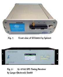
The record replay system GSS6450 is a portable unit capable of recording 4 GNSS bands simultaneously at all L band frequencies, including IRNSS (Indian Regional Navigation Satellite System), SBAS, Inmarsat, QZSS (Quasi Zenith Satellite System), B3, and Galileo E6. On record, the RF signals, are downconverted, digitized and stored at IF and can later be faithfully replayed with minor losses of 1-2 dB. “On playback, the IF signal is recreated and then up-converted to RF at the relevant GNSS frequency using the same built-in oven controlled local oscillator (OCXO) as used to record the data for minimum phase noise.” [8]. RF signals can be recorded at 4, 8 or 16 bit for quantization and at 10, 30 and 50 MHz bandwidth. There are throughput limitations at 8 and 16 bits and 50 MHz, limiting the amount of channels that can be recorded simultaneously to 1-2. [8]. The GSS6450 contains an OCXO for record and playback for high frequency stability. It is very small at 2.2 kg and a size of 21*20 cm, with a large storage capacity of 2-4 TB internal and external SSD. The disadvantage of recording at 8-16 bits and 50 MHz is a very high data volume, resulting in short maximum recording times of about 1 hour/TB. This recording time can be extended, by using larger storage media, for example recording externally via USB 3.0. [8].
At the same time, the major advantage of this record and replay system is the 16 bit depth for quantization of I and Q each, allowing to capture GNSS signals even at high jamming powers. Most other portable record and replay systems have a 2 bit quantization, which is suitable for general GNSS signals with a 12 dB dynamic range. Greater bit depth allows better resolution of GNSS signals and greatly increases this dynamic range both for jamming and for multipath and fading effects, to 21 dB at 4 bit I and 4 bit Q, to 45 dB at 8 bit I and 8 bit Q and to 80 dB at 16 bit I and 16 bit Q.
Sampling rates are 10.23, 30.69 or 51.15 MHz, synchronous recording rate for external data is 300 kbps at 10.23 MHz, 900 kbps at 30.69 MHz and 1500 kbps at 51.15 MHz, asynchronous recording rate for external data is 4800-115200 baud. [8] The reference oscillator is an OCXO with a frequency of 10.23 MHz, to allow direct generation of the wanted GNSS frequencies. There are two RF outputs: one normal RF output with a standard
GNSS RF signal strength (nominal -130 dBm for GPS L1), and one high power output at the back of the test system with around -80 dBm nominal [8]. In addition there is a 10 MHz Reference IN port, allowing to input a source of precise timing. The better the timing, the better the accuracy of the GNSS Position, Navigation and timing solution.
“The GSS6450 is fully integrated and can be controlled from the front panel, over WiFi, from the webserver or via scripts. Remote control is possible via a VNC (Virtual Network Computing) server and HTTP (Hypertext Transfer Protocol) messages. [9].
“External data can be recorded synchronously and asynchronously. The wide range of external data sources includes: 4 video streams per webcam, audio, CAN (Controller Area Network) bus data, timing pulses, NMEA (National Marine Electronics Association) data, IMU (Inertial Measurement Units) and other sensors. [9]
Timing Systems
The signal quality of GNSS test systems depends directly on the quality of the timing reference. To improve the accuracy of the complete test setup, the network of record and replay systems is triggered centrally by a high precision timing unit, so that the trigger pulse arrives at each recording system within 10 ns. It is possible to further enhance the quality of the recording of the GSS6450 units by input of a highly precise external 10 MHz frequency with better stability and accuracy than the internal OCXO, to compensate for various drift and aging effects of the oscillators.
We propose to use the LL-3760, a precision GPS Timing Receiver, with a basic accuracy of +/- 5 ns, based on a high quality OCXO [14]. This accuracy was verified in experiments in the AviationGATE (Aviation Galileo Testbed) at the Technical University of Braunschweig [14]. The unit outputs 10 MHz and 1 pulse per second synchronized to the GPS system.
Originally, the unit was designed to provide time and frequency to Spirent Pseudolite Simulators (Galileo) [12]. It provides “three capabilities to shift the system time independently, with a programmable shift of the 1 PPS and frequency outputs in ~25 ps steps, phase locked [12]. On the one hand, this enables triggering of the 4 record and replay systems within 10 ns, on the other hand it allows provision of a very stable 10 MHz frequency to keep the record and replay systems precisely synchronized, and on the third hand it provides very precise timing for one day with 500-600 ns drift per 24 hours, even in case of a loss of GPS/GNSS signals due to jamming or spoofing. An even higher accuracy can be achieved with a Rubidium standard instead of the OCXO.
In order to detect spoofing, it is also possible to integrate a timing and frequency monitoring card KL-3360 [19] by Lange Electronic for the detection of time jumps and offsets. This time and frequency unit monitors and compares time and frequency systems, it controls up to eight frequency signals from 4-40 MHz and up to eight 1 PPS Input Signals. It is programmable via PC (personal computer), with the Grafical User Interface “DataMon”. When the preset limits of permissible errors are exceeded the software releases an alarm, which is displayed and can be distributed via email and SNMP-trap (Simple Network Management Protocol) [19]. It offers three types of alarm messages: optical, via e-mail and SNMP trap. All data are stored on the PC and can be played back in different speeds in the „DataMon“ Software or analyzed in spreadsheets. This allows retrospective analysis of time- and frequency anomalies through stored data.
System Interconnections
The DETECTORS work independently of the other test system components and provide their information via webserver or local data base to the central data processing or navigation system. The timing receiver and the record and replay units are connected via coax cable providing 1 PPS and 10 MHz reference. This is possible for a length of several hundred meters. With an additional effort, the four 1 PPS outputs can be adjusted to the different cable lengths, so that the pulses will arrive simultaneously. The cable lengths must be known for this adjustment. The central data processing unit or navigation system can send a trigger pulse to the record and replay systems via the precise GPS timing receiver. Or the precise GPS timing receiver LL-3760 can send the trigger on its own.
Use cases
The proposed concept can be used in any traffic applications involving safety critical operations, where human lives are at stake, on large vehicles or vessels, both in the civilian and the military domain.
Here we want to highlight the use case of timing on military ships, which is crucial for several important subsystems and is maintained with great effort. Military ships and vessels are usually equipped with several GNSS receivers on-board, used both for timing and positioning. During field operations a jamming or spoofing attack is more likely than in civilian ships. Communication is based on frequency hopping and all parties taking part in the communication need to stay synchronized within 100-200 μs.
With our proposed GPS timing reference, timing drifts 500-600 ns in 24 hours, and timing of about 15 μs accuracy can be maintained for 30 days, even in case of long-lasting jamming and spoofing attacks, as the internal Rubidium oscillator(s) continues to operate with a high stability, independent of external RF signals. The requirement of 100-200 μs timing accuracy is still met after 4-5 months of free running Rubidium oscillator without any GNSS reception. Depending on the quality of the oscillator, an even higher accuracy can be achieved (Cesiums, Masers or multiple Rubidiums).
Commercial container ships transport freight of high value, and are sometimes kidnapped and robbed. It is useful to have an early warning system for jamming and spoofing on-board, indicating that an attack might be imminent.
Timing and integrity monitoring is critical on test ranges and airports, both military and civilian, where quick alerts are required for secure operation, e.g. an approaching aircraft needs to receive integrity information within 6 s according to ICAO (International Civil Aviation Organization) require-ments.
Benfits and Drawbacks
Advantages
▪▪ The overall system outputs a fast alert in case of interference and spoofing, so that immediate action can be taken, e.g. fallback on backup systems.
▪▪ With 2 DETECTORs the direction of arrival of the jammer can be determined
▪▪ This system enables a 3D spatial recording and capturing of the GNSS and interference signal environment.
▪▪ The GNSS and interference signals are captured immediately following the alert, giving a better chance for classification, identification of nature of inter-ference, multipath and repeated patterns, and finding the root cause of GNSS reception problems.
▪▪ The RF signals are recorded and can be replayed repeatedly, so that a deeper analysis can be carried out in the laboratory.
▪▪ The data allow conclusions about quality of the location of the GNSS antenna on the shell of the vehicle
▪▪ The LE 3760 keeps operating and providing a very precise time during a jamming or spoofing event. The precise time is maintained by the internal oscillator:
▪▪ This precise time can be used on-board military and other ships to continuously synchronize all devices and systems
▪▪ It allows monitoring of the time with a precise timing receiver, or a time and frequency monitor. Unusual shifts or offset in the time, indicate the presence of a spoofing attack, so that an alert can be triggered by the software of the frequency monitor.
Drawbacks
▪▪ High effort and a significant investment initially
▪▪ It takes more than one detector and Record and Replay unit to determine the direction of the interfering signals
▪▪ It takes time to analyze signals – unless there is an algorithm capable of automatic evaluation of signals
▪▪ Interference can be caused by different phenomena from different sources: Multipath, spoofing, atmos-pheric effects and jamming, and more. They can be recorded with the same Record and Replay system. The analysis method and recognition algorithm needs to be different for each of them
Conclusion
Positioning, Navigation and timing with satellite navigation, is an important component of many safety critical applications, e.g. timing on military ships, boats and trucks to enable secure and complex communication schemes. Due to their low signal power, GNSS signal reception can easily be degraded and disrupted by interfering signals, like jamming and spoofing.
In this paper we propose a jamming and spoofing detection test system comprising one or two jamming detectors and a network of record and replay systems, triggered centrally by a high precision timing unit, plus a time and frequency monitoring card. The monitoring card detects time jumps and thus spoofing.
Jamming detectors work independently and are able to monitor the signal environment non-stop, to detect jamming events, classify them and send alerts, in case of strong interference. 4 record and replay systems can be triggered by a central unit and faithfully record the RF of both the GNSS signals and the interference signals with high bit depth and fidelity.
The central high precision timing unit ensures that the trigger pulse arrives at each recording system with a time difference of less than 10 ns, enhancing the accuracy of the recording of the complete test setup. It is possible to improve the quality of the recording even further by input of a highly precise external 10 MHz frequency with very high stability and accuracy.
The overall setup allows to replay the GNSS signals, either on board the vehicle within a few minutes delay after the detection of a GPS/GNSS denial or later in the laboratory and thus to reconstruct a 3D view of GNSS signals and other signals in the L-Band on the large vehicle.
In this way, navigators are alerted to critical jamming and spoofing events in real-time, they have access to a concise overview of critical events in a database table on a screen, and gain the ability for an in-depth analysis of the complex signal environment by replaying the recorded signals in near-real-time after the alert. The main advantage is that precise timing can be maintained for many days, the duration depending on requirements. In the case of the military communication the duration is up to 4-5 months with the OCXO.
Acknowledgment
I would like to thank Julian Kemp and Romain Zimmermann from Spirent Communications for helpful comments.
References
M. Stanisak, K. Hünerbein K, U. Bestmann, W. Lange, “Measured GNSS Jamming Events at German Motorways”, Proc. of POSNAV ITS, DGON Conference, Berlin, Germany,5th-6th July, 2016.
K. Hünerbein, W. Lange “Real Life Evidence for Spoofing and Jamming of GNSS Receivers”, Conf. Proc. of CerGal, DGON Conference, Darmstadt, Germany, 7th-8th July ,2015.
D. Shephard, J. Bhatti, T. Humphreys, “Drone Hack: Spoofing Attack Demonstration On a Civilian Unmanned Aerial Vehicle”, GPS World, Aug 2012, vol. 23, no. 8, pp. 30-33.
M. Jones, “The Civilian Battlefield”, Inside GNSS, March/April 2011, vol. 6, no. 2, pp. 40-49.
K. Sheridan, “Interference Detection and Characterisation using a Software Receiver: The Detector Project.” Presentation at the 7th Annual GNSS Vulnerabilities and Solutions Conference, April 18th-20th, 2013, Baška, KRK Island, Croatia.
Spirent Communications, “GSS200D GNSS Interference DETECTOR”, Datasheet with Product Specification: MS3103 Issue 2-00, March 2017.
M. Pölöskey, C. Hoelper, K. Sheridan,”Detector: Fingerprinting GNSS Threats.” Presentation at POSNAV ITS 2013 in Berlin, 29th Nov, 2013.
Spirent Communications, “Spirent GSS6450 Multi-frequency Record & Playback System”, Datasheet with Product Specification: MS3098 Issue 2-02 March 2017.
K. Hünerbein, W. Lange, “Testing of GNSS Receivers with Recorded and Replayed Signals of Multiple Constellations” Proc. of Cergal 2014, DGON Conference, Dresden, Germany 08th-09th July, 2014.
S. Hickling, T. Hadrell T, “Recording and Replay of GNSS RF Signals for Multiple Constellations and Frequency Band” Proc. Of ION Conference, 2013, Nashville, TN
L. Scott, “Protecting Position in Critical Operations: Jamming Signals Criminal Activity in Intermodal Ports” GPS World, May 2015, pp. 49-50.
Lange-Electronic GmbH, “LL-3760, GPS Timing Receiver”, Datasheet, V 2.1 .
U. Bestmann, M. Steen, P. Hecker, A. Konovaltsev, M. Heckler, F. Kneissl, “Aviation Applications: Hybrid Navigation Techniques and Safety of Life Requirements, Part 1” Inside GNSS, June 2010, pp. 64-72.
U. Bestmann, B. Wulfen, P. Hecker, F. Kneissl, V. Kropp, “Aviation Applications: Hybrid Navigation Techniques and Safety of Life Requirements, Part 2” Inside GNSS July/August 2010, pp. 62-68. S. Pullen, G. Gao, “GNSS Jamming in the Name of Privacy” Inside GNSS March/April 2012 pp. 34-43. J. Grabowski, “Personal Privacy Jammers: Locating Jersey PPDs Jamming GBAS safety of Life Signals” GPS World April 2012, pp. 28-37. H. Borowski, O. Isoz, F. Eklöf,
S. Lo, D. Akos, “Detecting False Signals with Automatic gain Control” GPS World April 2012, pp. 38-43.
K. Hünerbein W. Lange, “A New Solution of Generation of Spoofing Signals for GNSS Receivers” Conf. Proc. of Cergal 2014, DGON Conference in Dresden, Germany 08-09 July 2014.
Lange-Electronic GmbH, “KL-3360 Time and Frequency Monitor” Datasheet, 2016.


 (No Ratings Yet)


Leave your response!