| Mapping | |
Continuous high precision navigation
Using MEMS inertial sensors aided RTK GPS for mobile mapping applications |
|
 |
|
|||||
 |
|
|||||
 |
|
|||||
 |
|
|||||
 |
|
|||||
In a modern mobile mapping system, the navigation component usually consists of a GPS receiver and an inertial navigation system (INS), which can provide accurate geo-referencing to the imaging sensors [1][2]. To achieve centimetre-level positioning accuracy, RTK-GPS is a natural choice. However, RTK-GPS in urban areas suffers from frequent outages due to blockages of either the GPS signals or the reference station radio links. In addition, multipath from buildings, trees and heavy vehicles could degrade the accuracy of the GPS when the vehicle is near them. Integration of an INS and GPS can bridge the GPS outages and maintain accuracy over short time periods, but a high–precision INS is too expensive for many land vehicle applications.
Keeping in mind that many mobile mapping practioners already have the RTK GPS devices, the ideal system configuration would be that such users simply plug their RTK-GPS receivers into an integration device, which has built-in MEMS inertial sensors and can integrate the two data streams when they are available. The integration device should be something like a “universal” box that has sufficient flexibility to be compatible with many different RTK-GPS receivers.
This paper describes the “NavExplorer”, a low-cost GPS/INS integrated system which uses inexpensive MEMS inertial sensors and RTK-GPS to balance affordability and accuracy, providing a continuous, high accuracy navigation solution. To achieve maximum flexibility, field programmable gate array (FPGA) technology is used to implement the integration device. The FPGA approach allows us to easily configure the logic and software of the system without any changes to the hardware components of the integration device when it is connected to a different GPS receiver.
By integrating the NavExplorer with the PGR Ladybug panoramic camera and Multiple SICK laser scanners, a mobile mapping system has been developed for the Taipei 3D Urban Reconstruction. NavExplorer generates position data for precise 3D object geo-referencing. The NavExplorer consists of a MicroStrain inertial sensor, unit and a Trimble RTK-GPS receiver. The Trimble receiver outputs the position solution in either RTK- or standalone GPS when the RTK corrections are unavailable. With the Trimble operating in the RTK-GPS mode, the integration solution achieves centimetre-level accuracy. This accuracy can be maintained for a short period of time when the RTK corrections are blocked. With the integration Kalman filter, the NavExplorer can provide accuracy to a reasonable level when the host vehicle is driven in a tunnel or operated in an environment of frequent GPS outages. The performance of a GPS/INS integrated system during GPS outages is an excellent indicator of the successful design of the system [3].
Many road tests have been conducted in Sydney and Taipei to evaluate the performance of the NavExplorer. The results indicate that the NavExplorer can maintain good GPS accuracy in multipath environments, and provided smooth and continuous solutions in tunnels when the GPS signals have been completely lost.
2. Configuration of the system
2.1 Hardware components
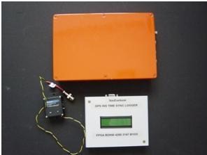
The hardware components of the NavExplorer consist of a Trimble BD950 GPS receiver, a MicroStrain 3DM-GX2 MEMS inertial sensor unit, and an FPGA-based time-sync data logger, as shown in Fig 1. The time-sync data logger collects the GPS and INS data and stores them on a SD card. In addition to accepting a PPS input for precise time synchronisation, the NavExplorer also provides PPS output for time synchronisation of other components of the mobile mapping system.
Fig. 1 The hardware components of NavExplorer
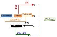
The hardware connections are detailed in Fig. 2. The PPS output of the BD950 is at 7.2v/50ohm, which is converted to a TTL level, which is fed into the time-sync data logger for time synchronisation of its internal clock with GPS time. The PPS signal is also split for output for other devices. It is fed into the 3DM-GX2 in the current configuration to trigger its sampling. The 3DM-GX2 and BD950 are connected to the time-sync data logger via the ports COM1 and COM2. The radio modem is connected with the BD950 via the port COM3.
Fig. 2 Illustration of hardware connections
2.2. Operation of NavExplorer
The BD950 and 3DM-GX2 are configured to output the data at 10Hz and 20Hz respectively. The operation status of the NavExplorer will be displayed on the LCD screen of the data logger. Three flags indicate all the data of INS, GPS, and PPS are being received by the data logger. The button on the data logger controls start/stop of logging data on the SD card. The logging status is displayed on the LCD screen.
The Files: Three files are written to the SD card for each logging session. These files are named as “GPS_x.BIN”, “INS_x.BIN” and “PPS_x.BIN”, where “x” corresponds to an index number of the logging sessions from 0 to 9. The data are recorded in the binary format.
The Button: The button controls SD card mounting and data logging. When the device is powered on data inputs from the two serial ports and the PPS will be displayed on the LCD. When the button is pressed the SD card will be mounted and new files will be created if the SD card is mounted successfully. The data is then logged to the SD card. When the button is pressed again, the current logging session will be terminated, and the card is unmounted and can be removed from the device.
The LCD screen: The LCD displays operation status of the device, and the data input from the GPS, INS and PPS. The indicators of data input flip once when new data arrives. The total bytes of the incoming data is displayed and updated from time to time.
2.3. The software package
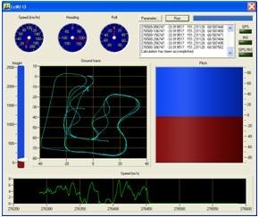
NavExplorer’s software package “LCIKF” (loosely-coupled integration Kalman filter) can post-process the recorded data to achieve the highest possible accuracy from an integration of GPS/GNSS and INS. With its loosely-coupled integration design, the NavExplorer can support a wide range of GPS/GNSS receivers and inertial sensors. A screen shot of LCIKF is shown in Fig. 3.
Fig.3 Screen shot of LCIKF
Pages: 1 2


 (3 votes, average: 1.67 out of 5)


Leave your response!