| Mycoordinates | |
Multiple reference station GPS networks for airborne navigation
|
||||||||||||||||||
|
Interest in the use of Global Navigation Satellite Systems (GNSS) as a main source of navigation reference is increasing. The system employed for such a purpose should be capable of meeting the requirements of air navigation in terms of accuracy, availability, integrity, and reliability. At present, the accuracy requirements for all ?ight categories up to precision approach are summarized in Table 1. The accuracy requirement for Category I can be achieved most of the time using wide area differential systems such as the American “WAAS”, the European “EGNOS”, and the Japanese “MSAS”. The American Federal Aviation Authority (FAA) is developing a Local Area Augmentation System (LAAS) for categories II and III, involving the ?nal and precision approach phases of ?ight. The system includes at least four reference GPS receivers located at each airport, whereby GPS measurements are collected and processed in real time. The computed GPS differential corrections are sent to aircraft via a (VHF) radio link to calculate its location. LAAS preliminary test results have generally demonstrated accuracy of less than 1 meter. However, the percentage of system availability is still under evaluation. The cost of establishing LAAS for major airports is expected to be significant.
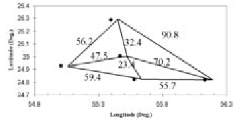
Multi-station RTK networks in airborne navigationExisting Real-Time Kinematic (RTK) multi-station reference networks can be used as an alternative to the airport LAAS to aid accurate positioning of aircraft during precision approach, takeoff and airport surface navigation. These systems were originally developed for surveying applications. In principle, observations from multiple reference stations covering a large area are gathered and processed in a common network adjustment at a central processing facility and measurement corrections are computed. The corrections are optimized for the coverage area to account for distance dependent errors. A single rover GPS receiver receives these measurement corrections from the control centre of the network and uses the corrections to estimate its position in real-time accurate to the cm-level with fixed integer carrier-phase ambiguity resolution, or to the sub-meter level with a fioat solution. The use of these networks in airborne navigation can be done by mounting the rover receiving the network corrections on the aircraft to determine its positions during flight. The feasibility of this approach is discussed in this article. AdvantagesThe advantages of using multistation reference RTK networks for precise airborne navigation are: • The multi-station reference networks service can extend to several tens or hundreds of kilometres, thus, each network can cover more than one airport, including small airports, unlike the airport LAAS. In addition to airport navigation, the system can be used in search and rescue operations, emergency landing, road traf?c control from the air, • RTK networks provide cm to decimetre positioning accuracy even in the case of malfunctioning of some stations. This situation is however more critical in airport LAAS due to the low number of stations used. • Compared to LAAS, no significant additional infrastructure cost is involved as the hardware and software of the GPS-RTK networks are available in most developed countries and the establishment of new networks is currently underway (or planned) in different regions worldwide. • RTK networks can give better runway utilization by improving airport surface navigation. The DVRS network as an exampleThe feasibility of using real-time reference networks for precise positioning in navigation is investigated using a network known as the Dubai Virtual Reference System (DVRS), located in Duabi, UAE. The DVRS network consists of five active reference stations (Figure 1), with baseline lengths varying between 23.4 km and 90.8 km. To compute its position, the rover receiver sends its approximate position via a cellular message to the network control centre where computations are carried out for each user. The estimated network measurement corrections are interpolated for a virtual reference station (VRS) close to the rover position and instantly sent to it. Previous testing of the DVRS system for kinematic ground surveying showed that system positioning accuracy was typically 1-2 cm in planimetry and 3-5 cm in altimetry. For accurate determination of aircraft heights from the ground using GPS-derived ellipsoidal heights, a recently established accurate geoid model for Dubai was utilized. Fig.1 The DVRS Network Concerns / recommendationsThe duplex communication approach used for the DVRS network puts a restriction on the number of users, as this number is limited by the ability of the control centre to simultaneously perform calculations for different users. The problem can however be alleviated by using a one-directional communication method. In this case, one or two ground transmitters (repeaters) at the airport will be established; they will receive the reference-station measurement corrections from the control centre on-line and send them to the aircraft via VHF modems. The receiver on board the aircraft will then interpolate the corrections at its location. Thus, no restrictions exist on the number of users. The establishment of ground transmitters at the airport can also improve the current availability of the corrections. Concerns related to the use of RTK networks in airborne navigation include: • Due to the high dynamics involved in airborne navigation, a high update rate of sending the corrections is needed compared with that implemented for land applications, which currently range between 5 and 70 seconds. • The format of GPS measurement corrections should be standardized to ensure that the system is independent of any single receiver manufacturer. This can be solved by adopting the RTCM standard for RTK multiple reference stations v3.0. • The integrity of the system should be continuously monitored, and methods should be implemented to warn the pilot against any deficiency in the system. |
||||||||||||||||||
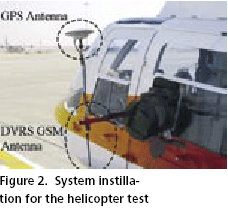
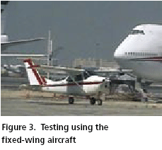
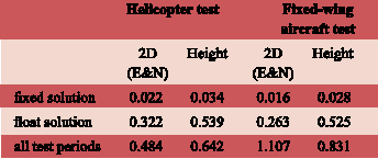
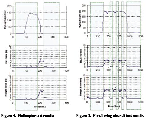
Testing the DVRS systemSeveral flight tests were conducted to study the use of the DVRS network for aircraft navigation. Two types of aircraft were used, a helicopter and a small fixed-wing airplane. A dual-frequency GPS rover receiver (Leica SR530) equipped with a DVRS GSM modem to receive the DVRS corrections was used. The test included the aircraft takeoff, enroute flying, landing and airport surface navigation. The data were processed at one-second intervals. In the helicopter test, the GPS and GSM antennae were rigidly mounted on an arm approximately 0.9 m long extending outside the helicopter. The arm was attached to a frame rigidly fixed inside the helicopter. No arm vibration was experienced during flight. For better GPS as well as GSM signal reception during testing, the GPS antenna was mounted high on the arm for better visibility of the sky, while the GSM antenna faced down. Figures 2 and 3 show the system installation on the aircrafts. For the fixed-wing aircraft test, the GSM antenna was installed inside the aircraft, which is acceptable for GSM communication. Both tests were carried out over the city of Dubai. Figure 4 and 5 show the helicopter and the fixed-wing aircraft flying height and the 2-D and height positioning accuracies achieved during testing. The DVRS corrections were continuously received (dashed region in the Figures) during major parts of airport surface navigation, takeoff, enroute flying, landing and parking. During some periods, temporary loss of the signals took place. This can be mainly attributed to the use of GSM signals in sending the DVRS data, and partially to changes in the aircraft dynamics. In general, the carrier phase measurement ambiguities were resolved as integers and the average positioning accuracy, represented by coordinate standard deviations, were on the cm-level as shown in Table 2. During the periods where the DVRS corrections were received but the ambiguities were resolved in a float solution, the positioning accuracy was at the sub-meter level. However, when the DVRS signals were not received, errors grew to more than 3.5 m, which are only suitable for category I navigation (enroute flying). Solutions to the problem of breaks in reception of network correctionsIntegration with the Inertial systemOne method to increase the availability of the positioning accuracy at the required level is to integrate GPS with an Inertial Measuring Unit (IMU). For testing purposes and due to hardware availability, a Honeywell tactical-grade (medium accuracy) IMU system of approximately 1-10 degrees/hour gyro drift was used. For simplicity, the GPS/INS integration was carried out in a decentralized loose coupling scheme. In this approach, the GPS and IMU (INS) filters ran independently in parallel. An adaptive Kalman filtering approach was employed in the processing of the test data. An integrated GPS/INS system is also beneficial in the sense that it gives high frequency output. In addition, the INS is useful for determination of the attitude information of the aircraft, as well as cycle slip detection and repair, and ambiguity resolution, if a centralized filtering scheme is used. The test results showed that the accuracy requirements for precision approach (category III) were generally achieved up to 25-31 seconds of the GPS data outages. This was dependent to some extent on the aircraft dynamics. Prediction of the measurement corrections as a time seriesIntegration of GPS with an Inertial Measuring Unit (IMU) to bridge positioning during short breaks in reception of corrections is only a valid solution for a short period. This is due to the rapid deterioration of the IMU positioning accuracy in the standalone mode, as well as the increased cost and complexity of the hardware and software involved. Another approach is proposed for this task where all error components including corrections to the wet tropospheric error, the satellite orbital and clock errors are individually estimated at the rover. During data reception from the reference stations, the corrections are continuously modeled as a time series and accurately predicted for several minutes ahead. The double exponential and ARIMA models were used for this purpose. When a loss of reception of the reference station data takes place, predicted measurement corrections are added to the un-differenced observables, and accurate positioning is carried out in an autonomous precise pointpositioning mode. Testing of this method showed that after 10 minutes of prediction, the positioning errors were still in the range of a few decimetres, and it was sufficient for Category III of navigation. ConclusionsThe test results show that the use of RTK multi-station reference networks (e.g. the DVRS network) in precise aircraft navigation is feasible, particularly for the airport area. This new technology can increase the coverage area compared with other GPS-navigation systems, such as airport LAAS, with significant cost reduction. Small airports can thus benefit from this service. Efficient methods for bridging positioning should be implemented when reception of network corrections is interrupted. This can include integration with IMU or predicting the measurement corrections as a time series. |
|||||||||||||||
|
|||||||||||||||
|
Pages: 1 2



 (No Ratings Yet)