| Applications | |
Terrestrial laser scanning helps to reconstruct a damaged train
This article describes the implementation of terrestrial laser scanning (TLS) in the accurate documentation of a damaged train wagon after a derailment accident |
 |
|
 |
|
Railway safety
Trains remain one of the safest ways to travel in Europe, where millions of euros have been sunk into rail safety and infrastructure. According to the European Railway Agency (ERA), trains are far safer than most other forms of transportation within Europe and about as safe as air travel (Table 1, ERA, 2013).
Recent studies regarding the train accident rate within the European Union show that the rate of fatal incidents has been declining steadily (ec.europa.eu / eurostat/ Transport_ accident_ statistics). The majority of the accidents involve cars crossing train tracks and not mass derailments such as the rail accident in Spain on July 2013 with 80 people killed, the high-speed TGV train derailment near Strasbourg in France killing 11 people on November 2015, and most recently in Spain on September 2016 killing 5 people (https:// en.wikipedia. org/ wiki/ Lists_of_rail_accidents).
Train incidents are classified into three groups: collisions with objects (i.e. crossing incidents), single train events (i.e. derailments), and train-to-train collisions. Regardless the type, the collision energy in a train crash is generally very large and causes significant damage on the train structures. An interesting point is that, unlike in the car industry, there are no European safety regulations covering vehicle design in the railway industry. All countries conform to the recommendations of the International Union of Railways on crashworthiness but adopt different structural specifications. Trains have, in most cases, been designed to crumple in a crash, to dissipate the enormous amount of energy released by the impact.
Train accident documentation
Recording a vehicle scene accident can be of two types; in situ documentation of the actual accident scene immediately after the accident and a post-accident mapping of the vehicle involved. The former is usually most relevant to automobile traffic accidents where it is very advantageous to know the condition or state of a car and to analyze data of, for example, acceleration, angular velocity, etc. of the vehicle at the accident occurrence time. Transitory events, e.g., accident scenes in particular, must be accurately and quickly recorded in situ prior to the removal of the affected vehicles. The second type refers to the detailed mapping of vehicles after their transfer from the scene of the accident to special repair sites. In the field of accident reconstruction, it is often important to measure the deformation of large sized vehicles (e.g. train, truck) after a crash has occurred. The measurements must be of high detail and accuracy to lead to conclusions including whether the vehicle is repairable, what kind of repair is needed and other useful information e.g. energy calculations, speed, etc.
Current methods of reconstructing accidents include total stations and laser rangefinders. With the advances in computer vision, 3D measurements are used offering a fast and detailed capture of complex environments that can help reconstruction experts in various types of analysis including crush deformation, impact configurations, and analysis of vehicle components. Close-range digital photogrammetric systems and terrestrial laser scanning provide such 3D data sets where timing and accuracy is critical (e.g. Behring et al., 2011; Randles et al., 2010; Du et al., 2009; Pagounis et al., 2006).
Accident description
The specific train accident described herein occurred on 22nd February 2008 at 12.30 pm, in the depot (parking and maneuvering) Station of Piraeus in Greece. The passenger train of the Urban Rail Transport Company of Athens comprised six carriages and was stationery prior to the accident. Cleaning personnel was only in the carriages for the routine cleaning. Due to human error, the lever – brake of the train was released and the train started moving and changed track lines covering a distance of about 300m. Then it was cruising uncontrolled at a speed of 40km/h and collided with a wall fence. The train dragged part of the wall and continued its unregulated course towards a busy street with cars and pedestrians (Figure 1). The end result was the loss of one pedestrian, injury of six cleaners working inside the train and serious damages on the protective wall and the train carriages.


From the six train carriages, the first three suffered major damage which was not repairable, the fourth suffered extensive damage but was repairable, and the last two had no damage. For this reason, it was important to have a full geometric documentation of the exterior and interior of the fourth carriage and provide a deformation model in order to assess the extent of the damage. The unique, complex shapes of the damage on the wagons made capturing and analyzing the deformations using traditional methods, such as tape measures and mechanical profilometers, very difficult.
Data processing
The data collection of the damaged carriage was performed with a Leica Scanstation 2 terrestrial laser scanner. The scans were acquired using a number of reflective targets placed on the external surface of the carriage to enable the georeferencing and registration process of the collected data (Figure 2). In order to avoid gaps and noisy data in the final model due to the large number of window openings, these were covered by paper. The scan acquisition was accomplished within 5 hours, obtaining about 9 million points.

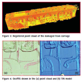
The scan registration was performed using the proprietary software Cyclone (hds.leica-geosystems.com) with a precision of 3mm. The processing includes the transformation of all point clouds from the local scanner coordinate system into the common coordinate system using the targets as tie points. The registered point cloud of the object is shown in Figure 3. The modelling process was performed in the proprietary software Geomagic (www. geomagic.com). The first step involved filtering for the removal of outliers and noise from the dataset. Redundant information is also removed at this stage. For noise removal, the free form shape algorithm was chosen after several trials. The associated statistics for the filtering is average distance of 0.0011m and standard deviation of 0.0009m. The full point cloud was also resampled by about 10%. This essentially reduces file sizes and ultimately lowers processing times for the modelling algorithms.
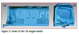
The creation of the TIN (triangulated irregular network) was performed in Geomagic, but the resultant surface had many gaps and other irregularities. The small gaps due to data missing were filled in using suitable filtering algorithms. There are cases however where the algorithms produce results that do not always correspond to the real surface. An interesting example is given in Figure 4 which shows the point cloud of a selected part of the external surface with graffiti drawings and the corresponding TIN model indicating these as deformations. This can happen because intensity values, which are registered by a TLS for each point of a 3D point cloud in addition to its coordinates, are affected by the characteristic of the measured object and the parameters of the environment (e.g. Pfeifer et al., 2007). The backscattered electromagnetic signal is influenced in its strength by the reflectivity of the scanned object surface, the incidence angle, the distance between laser scanner and object and the atmospheric specific setting of the TLS-measurement.
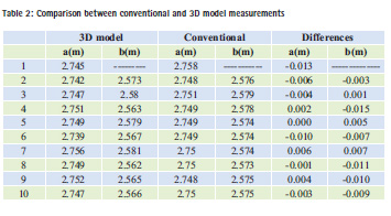
For this reason, a process is followed which fills the holes taking into consideration the complex geometry for specific parts of the object. The final model was also reduced further in size totalling to about 3.3 million triangles. Views of the final wagon model are shown in Figure 5. Clearly the front part of the wagon suffered most of the damage.
Deformation measurements
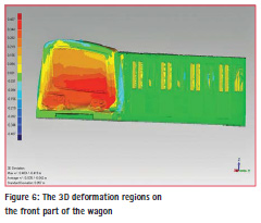
The 3D model created for the wagon was used to quantify the damage by measuring a number of profiles and sections. Crush along one horizontal axis and front-end shift or longitudinal bowing in a side impact are also measured. Additionally, the measurements from the model were compared with respective conventional measurements. The conventional measurements were carried out by the Urban Rail Transport Company of Athens (ISAP) in 2D by using tape measures and mechanical profilometers at specific sections along the wagon and height differences in selected parts of the frame. For each section, measurements of the lowest frame point (noted as ‘a’) and the top part of the roof (noted as ‘b’) were used. In Table 2, a comparison is given for the values of ‘a’ and ‘b’ for a number of sections between the measurements provided by the 3D model and the conventional methods.
The maximum difference is 1.3cm and the rms is 0.008m. It is seen that there is a fairly good aggreement of the results considering that there is a practical difficulty in identifying the exact sections between the two methods of measurements. The main disadvantage of the 2D deformation retrieval is that selected points on the damaged surface are examined. Instead, the use of a 3D high density model is more advantageous as it provides information about the deforming areas from the entire object’s surface. For this reason, the deformed wagon model was compared with the undeformed model of the same wagon. As there was no available point cloud data of the wagon before the accident, a CAD model was constructed based on the design plans for the specific type of wagon. The two models (undeformed and deformed) were aligned using a number of correspodence points.
A comparison between the two models in the form of deviations is shown in Figure 6. The example shown here was performed in Geomagic but there are open source software suites that provide similar tasks (e.g. Cloudcompare). The statistics of the 3D comparison gave a maximum difference of 0.4m with a standard deviation of 0.0507m. The colour variation provides the deforming regions in the front part of the wagon.
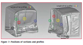
For a detailed examination, a number of longitudinal and sectional profiles were constructed along a predefined axis (Figure 7). The result is a 2D representation measurement in the vehicle X-Y plane at prescribed heights. This method of vehicle measurement conforms to those used in vehicle damage analysis (SAE, 1980). Example of profiles for lines 1 and 2 ( cf. Figure 7) are given in Figure 8 and 9.
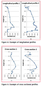
Both the 2D diagrams and the 3D comparison provide comparative results with respect the undeformed model of the train. It is important to emphasise that the undeformed model is lacking in reliability because it was created based only on design plans. The alignment of the two models is based on the identification of corresponding points in both models. Therefore, the high value of rms at 5.7 cm does not indicate the accuracy of the 3D model but rather the alignmnent of the two models. Nevertheless, the results show that this method has the advantages of high automation and 3D deformation quantification. Clearly, such type of qualitative information is difficult to retrieve using conventional methods of measurement.
Concluding remarks
The current technology for 3D recording using terrestrial laser scanning has reached a high level of development. The availability of this technique for accident reconstruction applications yields to several notable advantages. The created virtual model enables the investigator to look at the accident scene from different points of view and can be exploited to reproduce the event’s dynamics. Also, the digital set of data can be used anytime and shared among different operators. On the other hand, the acceptance of this type of data as valid and legal evidence is still to be recognised in many countries.
The field survey is not a trivial task, especially in the case of large or complex scenes. This requires the presence of experts to plan and carry out effective data acquisition. In the same direction goes the development of best practices, data interoperability and management and better understanding of the data quality needs for implementing terrestrial laser scanning for accident investigations.
The use of terrestrial laser scanning can add value to the achievable results. The good knowledge of the impact phenomena could not be achieved only by means of the traditional theoretical and analytical models used in crush analysis, because of the complexity of dynamic effects. Instead, the 3D models created by terrestrial laser scanning are able to virtually reproduce the bodies (vehicle, barriers, etc.), and be used to evaluate the deformations and dynamic actions exchanged during the crash.
References
Behring D., Thesing J., Becker H., Zobel R., (2001). Optical Coordinate Measuring Techniques for the Determination and Visualization of 3D Displacements in Crash Investigations. www.gom.com/fileadmin/user_upload/ industries/crash_testing.pdf
Du X., Jin X., Zhang X., Shen X., Hou X. (2009) Geometry features measurement of traffic accident for reconstruction based on closerange photogrammetry. Advances in Engineering Software 40(7):497-505, doi. org/10.1016/j.advengsoft.2008.09.002
European Railway Agency (2013) Intermediate report on the development of railway safety in the European Union. Publication date: 15 May 2013.
Pagounis V., Tsakiri M., Palaskas S., Biza B., Zaloumi E. (2006) 3D laser scanning for road safety and accident reconstruction. Proc. XXIIIth Int. FIG Congress, 8–13 October, Munich, Germany.
Pfeifer N., Dorninger P., Haring A., Fan H. (2007). Investigating terrestrial laser scanning intensity data: quality and functional relations.
Proc. 8th Conf. on Optical 3-D Measurement Techniques, 9-12 July, Zurich, Switzerland, pp 328-337.
Randles B., Jones B., Welcher J., Szabo T., Elliott D., MacAdams C., (2010). The Accuracy of Photogrammetry vs. Hands-on Measurement Techniques used in Accident Reconstruction, SAE International. www.photomodeler.com/arforensics/ documents/2010-01-0065.pdf
SAE International Surface Vehicle Standard (1980) Collision Deformation Classification. SAE Standard J224, Rev. Mar. 1980.


 (2 votes, average: 4.50 out of 5)


Leave your response!