| Surveying | |
Semi-buried seabed object detection: Sonar vs. Geophysical methods
This paper deals with the site investigation processes of detecting a semi-buried object using multibeam echosounder, sidescan sonar and magnetometer data |
|
|
|
|
|
The purpose of this paper is to conduct the evaluation of the object detection using sonar and geophysical methods. Increasing interest in maritime archaeology has led to a growing need for measuring techniques or innovative methods for detecting and identifying underwater objects. Object detection usually consists of two steps: feature detection and classification. In the feature detection step, the relevant features of the object to be detected are gathered. Here is the defintion of the feature provided by The International Hydrographic Organization (IHO). Standards for Hydrographic Surveys Special Publication 44 (IHO S- 44) defines a feature as ’any object, whether manmade or not, projecting above the sea floor, which may be a danger for surface navigation’. Moreover, ’S-44 sets minimum standards for surveys conducted for the safety of surface navigation’ and considers it the ’responsibility of each national authority to determine the precise characteristics of features to be detected’. Detection of objects occurs not only in the safety of navigation purpose, since finding such objects is the subject of interest for a wide group of professionals, including archaeologists, offshore construction specialists, and the military responsible for defending coastal waters. Challenge faced in this paper is detection of the semi- buried object, where we need to combine few survey methods in order to obtain reliable output results.
After first site investigation of the zone, sonar methods have been used only. When data interpretation has been done, it was clear that object has been partly buried under the seabed. Since there was a strong indication that object is cable, it has been decided to involve marine magnetic technique (magnetometer) in next investigation, since the primary use of the magnetometer survey (geophysical method) is to provide evidence of the existence of ferrous material on or below the seabed. Due to the disturbance of the surrounding structure, marine magnetic survey gave less information than expected. Therefore, results of the site investigation have been interpreted mostly using sonar survey methods, especially sidescan sonar survey data.
Survey methods used for site investigation
Sonar and geophysical survey methods have been used during the survey. Purpose of sonar methods is to determine depths and detect object on the seabed, while geophysical method has been used to give the information about ferrous object under the seabed level.
Sonar survey methods
Sonar (Sound Navigation and Ranging) uses sound waves to find and identify objects in the water and determine bathymetry. There is a wide range of acoustic imaging systems including multibeam echosounders, sidescan sonar, single-beam echosounders, interferometric systems and sub-bottom profilers. Since aim of this site investigation was to get results about bathymetry and object at the seabed, multibeam echosounder and sidescan sonar have been used during the survey. Data interpretation analysis has been performed using multibeam bathymetry and multibeam and sidescan sonar backscatter data.
Both multibeam echosounders and sidescan sonars can be used to collect acoustic backscatter data, the data obtained from the reflection of acoustic energy back toward a sonar device, where its intensity can be measured. With multibeam backscatter, there are no shadows because the sonar head is on the vessel’s hull and looking down over objects from a higher angle, instead of from one side or another. The high degree of bathymetric resolution and complete 3D coverage offered by these swath-sounding techniques is providing precise insights into complex sea floor geology and also allowing evaluations of dynamic sediment movements.
After various corrections are applied to the data, backscatter intensity is essentially a function of the seafloor’s physical properties, namely acoustic impedance, roughness (grain-size and small-scale topography) and volume inhomogeneity (variability in the thin layer of sediment penetrated by the acoustic signal).
Sidescan imagery is less prone to be affected by the slope of the seafloor as it can be positioned, whereas the multibeam can only receive the backscatter intensity as it reaches the survey vessel.
Sidescan sonars and multibeam echosounders both collect acoustic backscatter that can be interpreted to represent variations in seabed materials. Sidescan sonar systems are specifically designed for this purpose, whereas most multibeam echosounder systems that are presently in operation in connection with oil industry activities were designed to collect very accurate bathymetry, with backscatter data being a byproduct of the soundings. Conventional sidescan sonar systems (excluding more sophisticated systems, such as those that use interferometry, beam forming and synthetic aperture technology) do not measure water depth, but the images contain indirect bathymetric information in the form of an increase in backscatter when the seafloor slopes toward the sonar and a decrease in backscatter when the seafloor slopes away from it. The result is ‘acoustic shadows’ behind features with relief relative to their surroundings.
Since object at the seabed is cable, the size of which is not so significant, especially height, there is presumption that cable will be seen only after sidescan sonar acquisiton post processing.
Geophysical methods
Of the various geophysical technologies used for seabed mapping, the magnetic method has proved to be the most effective for locating ferrometallic objects masked by sea floor sediments, buried under the seabed or on the seabed surface itself. Important parameters to detect semi-buried cable using this method are its radius of ferrous emission and altitude of the magnetometer above the seabed during the acquisition. It is very difficult to detect underwater pipeline by conventional method, such as echo sounding and sidescan sonar method. Furthermore, the conventional acoustic methods cannot effectively detect seabed cable because the seabed cable is thin in size and often buried by sediments. On the contrary, the electromagnetic characteristics of seabed cable provide the possibility of detection by magnetism methods.
The ferromagnetic substance of seabed cable and the electrical current can produce an external magnetic field, its magnetic anomaly intensity (ΔT) is about 0.5-150 nT. Because the sensitivity of high resolution cesium vapor magnetometer can reach 0.005 nT (sampling rates at 1 Hz), the tiny change of magnetic anomaly produced by seabed cable can be effectively detected. Based on the characteristics of the magnetic field, the feature of the magnetic anomaly can be applied to analyze and identify seabed cable.
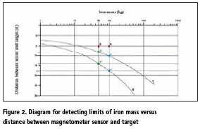
The detection limits are represented in the figure below. An object which is situated above’curve 1’will always be detected. An object which is positioned below ‘curve 2’ will not be detected.
Maximum detection depth of ferromagnetic objects, assuming an average magnetic susceptibility:
curve 1: anomaly treshold of 5nT (worst conditions),
curve 2: anomaly treshold of 1nT (ideal conditions).
Survey and methodology
Before each survey all the calibrations have been done (position verification, gyro check, absolute elevation check, multibeam patch test, sidescan sonar rub and wet test, USBL calibration). HiPAP 351P portable transducer for high precision acoustic positioning and underwater navigation has been used for the sidescan sonar and magnetometer positioning during this site investigation. Time difference between first and second site investigation survey is one year. After first survey when sonar methods (multibeam and sidescan sonar) were used, cable has been detected on several spots, only with sidescan sonar output results. Term ’Theoretical position’ has been used for the cable’s detected position during first survey. Analyzing output results, cable sections were visible only on sidescan sonar which led to conclusion that cable has been semi-buried. Another survey method had to be included in the investigation, and since interest was to determine cable section under the seabed, geophysical survey method was a logic solution.
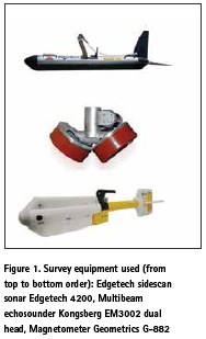
Multibeam survey
Kongsberg EM3002 dualhead provided primary bathymetric information at the survey location. In addition, as mentioned above, backscatter data has been recorded.
Multibeam survey has been executed on and around the theoretical position of the cable. No clear indications of the presence of the cable could be obtained. In post-processing, data has been double checked in 3D view to see if any linear irregularity became visible. Nothing could be found analyzing multibeam data which could indicate the cable presence.
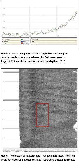
Additionally, multibeam data from the first survey has been compared with the processed data from the second one. When checking the cross profiles we can see that the general maximum depth (between the ripple marks) is slightly shallower in most recent survey (approx. 5cm). The sand ripple marks are little smaller in second site investigation, and have moved along the seafloor.
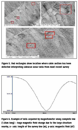
As multibeam systems acquire both bathymetry (depth) and backscatter (intensity) data, backscatter data has been post processed and no indications of the cable sections presence have been found. The reason of not detecting semi-buried cable using multibeam data is mainly cable dimension, while sonar method is not most suitable one for cable detection in general. On the figure below there is an example of the location where cable section has been detected interpreting sidescan sonar data. No semi-buried cable section was visible interpreting multibeam backscatter data.
Sidescan sonar
Edgetech 4200 sidescan sonar has been used during the survey. Towed behind the vessel on average distance of 80m. Since sidescan sonar range was 75m, average altitude of the towfish was 7 meters, while total coverage was 200%. The highresolution imaging of underwater environments afforded by sonar has proven particularly useful for the detection of objects on the seabed. During post processing procedure, all the cable sections have been double detected. As explained before, sidescan sonar has established itself as the predominant tool for imaging the ocean floor, giving good object detection and seabed character discrimination (Blondel and Murton, 1997). USBL calibration has been performed, to ensure correct positioning of the sidescan sonar and magnetometer system, while position accuracy after calibration is ± 1.5 m. The sidescan sonar data positioning is also checked during the post processing by comparing the multibeam data with the mosaic from the SSS. On the latest survey we were able to locate the cable outcroping seven times at different locations as seen on the following figures:
Magnetometer survey
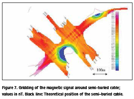
Geometrics model G-882 marine magnetometer was used to precisely measure the Earth’s magnetic field. Magnetometer has been towed behind the sidescan sonar towfish with layback of 10 meters. To eliminate the magnetic effect of the survey vessel, the magnetometer sensor is towed behind the boat at a sufficient distance of about 4 times the vessel’s length. During the magnetometer survey we had data interference due to the large structure presence nearby. According to it, there were no significant changes in the magnetic field which can indicate presence of the semiburied cable. Indeed, on the following figure no variations appear on the signal detected from the large structure.
We can see the changes in magnetic field from 48861 nT to 48686 nT, which is 175 nT. It has been expected to see on this amplitude caused by nearby structure, change in the magnetic field which indicates cable presence, but interference with the strcture is too strong, even at 200m distance, as shown in the figure below.
A strong filter has been applied to the data, to try to remove the influence of the structures. However, this didn’t give any reliable and useful result.
Sonar vs. geophysical survey
Final results of the site investigation were not expected. Since aim of backscatter data, especially sidescan sonar, is to give information about objects on the seabed surface, while the primary use of the magnetometer is to provide evidence of the existence of ferrous material on or below the seabed.
Various maritime survey methods, such as sonar, optical and magnetic technologies, are used for locating submerged artifacts. Marine magnetic surveys have been successfully used for mapping marine ferrous targets, for magnetic mapping of contaminated seabed sediments, and for mapping archeological structures. Of the various technologies used for seabed mapping, the magnetic method has proved to be the most effective for locating ferrometallic objects masked by sea floor sediments or buried under the seabed. Because the intensity of the magnetic field produced by a magnetized body drops rapidly as the distance to the measured point increases, tow fish configuration is widely used. There are, however, situations where the offshore structure in the survey area prevents the magnetometer survey to produce desired data, like during this investigation. Therefore, data interpreation had to rely on sonar methods, which provided enough information about cable exposure, length, cable sections, but not the total length and position which was the primary purpose of the survey.
Conclusion
The magnetometer, which was believed to be the better system for this work, didn’t give the expected results. The sidescan sonar output data showed only usable data about the cable shape and positon, because structure nearby does not affect sonar survey output results. Since the cable during second survey, has been detected also more to the north, it is likely that it extends over a much longer area. Nature of the semi-buried cable remains unknown.
On this example, it is obvious that several survey methods have to be combined during the semi- buried object detection. Since this survey showed that the large structure presented only interferences on the magnetic data and not the acoustic data, additional survey methods to be involved in this site investigation to get complete information about the semi-buried cable position. This imposes idea of including sub-bottom profile or sub-bottom imager survey method which is completely independant of the large structure influence in surrounding area.
References
De Jong, C.D., Lachapelle, G., Skone, S., Elema, I.A. (2002): Hydrogrpahy, Vereniging vor Studi- en Studetnenbelange te Delft, Delft, 2002.
International Hydrographic Organization: Manual on Hydrography, Publication M-13, 1st edition, May 2005
International Hydrographic Organization: IHO Standards for Hydrographic surveys, Special publication no 44, 5th edition, February 2008
Quintal, R., Dysart, P., Greene, R., “Automated Side-scan Data Analysis,” Hydro International, Vol. 11, No. 09, October 2007.
The paper was presented at FIG Working Week 2017, Helsinki, Finland, May 29-June 2, 2017.


 (No Ratings Yet)


Leave your response!