| Navigation | |
Outdoor mobile field robot navigation
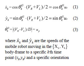
The automation of agriculture has become a significant concern due to the benefits of increased productivity and enhanced operational safety developed in 1997 [1]. In recent years, with the on-going development of mechatronic techniques, traditional manual work has been replaced by automated tools, such as the harvester, mower, and sprayer [2]. However, more specialized farming work still requires human manipulation of farming machinery. Thus, several techniques for applying guidance and radio navigation systems in agriculture have been investigated [3- 6]. In addition, numerous studies have addressed the topic of intelligent robots for greenhouse use, and the robotics industry has produced a wide variety of remarkable robots [7-10]. The development of a gardening robot with an autonomous navigation system is now regarded as an important advance in precision agriculture, as well as a promising alternative to the dwindling farm-labor force [11-13]. However, the outdoor environment provides very different circumstances from those encountered in the laboratory [14]. Natural environments are inherently unstructured; the ground may be hazardous due to uneven pavement, ramps, hidden rocks, branches and potholes, making safe passage almost impossible. Overcoming these difficulties requires accurate data related to position and attitude in order to ensure the effective application of a mobile robot in an garden or greenhouse setting [15]. The integration of an IMU with a RTK GPS can compensate for positioning errors associated with machinery attitude, and may provide more accurate navigational information for many field operations, such as sowing, tilling, planting, cultivating, weeding and harvesting. [4, 16-17]. These devices are sealed from the environment, which makes them more robust under harsh environmental conditions. Noguchi et al. proposed an agricultural navigation system comprised of an RTK GPS in conjunction with an inertial measurement unit [16]. The Kalman filters method is most commonly used in integrated navigation. Kalman filters offer a sound theoretical framework for the fusion of multisensor data, in which the position of the mobile robot is tracked at all times. Literature on the integration of IMU and/ or other sensors, with or without a GPS/ DGPS receiver, is widely available [17, 22-25]. These integrated systems are capable of enhancing positional accuracy; more importantly, they offer reliable short-term positioning information should the GPS suffer a signal outage. Although Kalman filter-based navigation techniques are effective to achieve highprecision positioning, the application field, environmental conditions, system complexity, and cost of hardware/software development should all be considered to achieve the required positioning accuracy at a low development cost. In addition, the integration of received sensor data within one controller is vulnerable to the following problems: 1) The program design of internal system requires extra attention. If the sensor data can not be received, idling occurs in the system and fails to function properly; 2) The use of single controller to achieve autonomous navigation will require the main core controller to execute every function in the system program, which takes long computation time to calculate. Thus, it will degrade the overall performance of the system. The use of more advanced signal processor will require more cost; and 3) Although such techniques are indeed capable of reducing positional errors resulting from robot movement, both system complexity and the cost of the robots are increased. The fuzzy logic concept began with the 1965 proposal of the fuzzy set theory by LotfiZadeh [26-27]. This approach addresses the imprecise nature of control issues within all physical systems. In recent years, fuzzy logic and expert system have been widely adopted in smart control systems, crop management, energy management, and finances, etc. [28-30]. Nevertheless, traditional fuzzy expert systems have to solve the problem of converting more complex problems into more complex expressions of expert knowledge. More the number of input variables and membership functions, more are the number of fuzzy logic rules. Thus, typical single-layer fuzzy inference systems are insufficient for complicated systems with a large number of input variables. It is shown that multi-layer fuzzy inference can reduce the number of fuzzy rules [31]. Kuo et al. established a three-layer parallel fuzzy inference model to shorten the time of inference calculation in the fuzzy controller [32]. The improved fuzzy neural network is able to conduct distributed processing. Nowadays, many literatures focus on obstacle avoidance and autonomous navigation by using fuzzy-based control method for mobile robot [33-42]. Among them, some scholars use the sliding mode controller to serve as motion controller, or the position error and angular error to serve as input variables of fuzzy controller. After the fuzzy inference process, the output signal of fuzzy controller is used to drive the two servo motors, which results in obstacle avoidance and navigation for mobile robot. However, these fuzzy-based techniques are only employed in indoor environment or simulation. Only a part of literatures use ultrasonic sensor or other sensors (such as compass, odometer, etc.) for mobile robot navigation. Meanwhile, uniform sensors are often utilized in fuzzy controller. None of them use the sensor integration method to improve the navigation performance for mobile robot. The development of micro-mechanics (MEM) sensors has expanded the potential of design techniques used for automated machinery; the most noteworthy of these are intelligent mechanical systems. That is, with respect to the current low-cost GPS receiver with precision ranging between 5 to 10 meters, some range sensors, in combination with shortdistance positioning techniques and GPS receivers, may be employed to achieve high-precision positioning. Some research results regarding mobile robots have been applied to many fields of agriculture [43- 47]. These methods utilized the MEM sensors to assist the robot in navigating autonomously, picking fruit or spraying safely, reducing the labor of farmers. Dead-reckoning sensors are inexpensive and dependable. They work by adopting a simple mathematical procedure to determine the current location of a mobile robot as it advances, at a specified velocity and over a given length of time, from a previously known position along a pre-determined course. The simplest form of dead reckoning is termed odometry and is based on the integration of information related to incremental motion over time, which results in an unbounded accumulation of errors [48-49]. To be more specific, orientation errors result in considerable errors in lateral position, which increase proportionally with the distance travelled. Laser-based sensors have a relatively long-to-short range and high resolution [50], and are used in the dual functions of simultaneous location and mapping (SLAM) and obstacle avoidance [51]. An electronic compass (EC) is a magnetometer that detects the magnetic field of the earth. ECs are typically employed to supplement other sensors. Benson, et al. [52] adopted an EC with GPS to guide a robot along straight lines. Thus, this research focuses on shortdistance detection techniques, using lowcost sensors and controllers to meet shortrange navigational demands. All sensors incorporated into the structure of the proposed mobile robot were controlled using multiple controllers embedded board. To ensure safety for the moving vehicle, the proposed vehicle is equipped with a laser range finder to avoid collision. The accelerometer, gyroscopes, and electronics compass are adopted to effectively correct the error of vehicle moving path. The Hallrotary wheel encoders can be combined with GPS to serve as an elementary dead reckoning in order to accomplish vehicle safe navigation through multi-layer fuzzy decision scheme. The proposed platform is designed to receive the multiple sensor data and integrated in multiple microcontrollers based on embedded concept. MethodologyThis section provides a dynamic mathematics model of a mobile robot, the design of the sensor-fusion scheme, and each of the devices required for the mobile robot to accomplish its tasks. Kinematics Model of the Mobile Robot In this paper, the speed difference between the wheels is utilized to control the moving direction of the mobile robot. An idler wheel is used to assist the robot in its movement. The kinematics model of the mobile robot is shown as follows [53][54]:
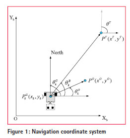
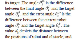
. Assume the target position to be PT (xT, yT), the final steering angle to be 0 T, and the obstacle position to be P0 (x0,y0). The value Lk denotes the distance between the positions of the robot and
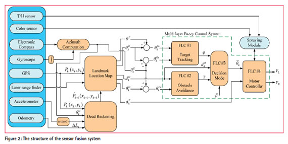
Multi-layer fuzzy logic controller The proposed scheme combines the multi-layer fuzzy controller with sensor modules, controller modules, and spraying module to form a sensor-fusion system for robot navigation, obstacle avoidance, and spraying. The system diagram is displayed in Figure 2. The sensor signals from the electronic compass and gyroscope were used to calculate the avoidance and traveling angles within the system. The location and moving distance of the robot were calculated using an accelerometer and an odometer. Static initial location information was received via the GPS receiver. The distance between obstacle and robot was detected and calculated using a laser rangefinder. The behaviors of path planning and obstacle avoidance were determined using four controllers: Target-tracking was performed by the first fuzzy controller (FLC #1); the second and third fuzzy controllers (FLC #2 and FLC #3, respectively) were designed to perform obstacle avoidance and decision making for the mobile robot; Finally, the speeds of the right and left wheels of the mobile robot were controlled via the fourth fuzzy controller (FLC #4). Meanwhile, the T/H and color sensors were used to find the crop target and to perform the spraying work.
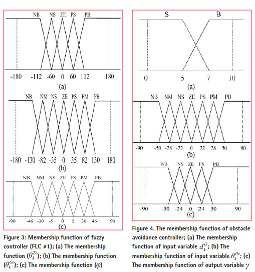
The design of a fuzzy controller depends on human experience, and does not entail excessive reliance on the mathematical model, which makes it a good method for intelligent control application [31]. However, the more complex the system, the greater is the fuzziness of the rules within the fuzzy controller [32]. In this paper, the multilayer fuzzy logic controller consisted of four sub-fuzzy controllers. The benefit of using this structure was to avoid increased input variables, which result in increased dependence on fuzzy inference rules. This method may effectively reduce the complexity and cost of the system. The design process for each controller resembled that of the traditional fuzzy controller. The design steps were as follows [53-54]: 1.) Define the number of input/output variables and linguistic labels; 2.) Select the strategies for “fuzzification”; 3.) Design the fuzzy rule table; 4.) Establish the fuzzy inference engine; and 5.) Select the method of defuzzification. In the proposed system, there were five input variables and two output variables to be selected. The value of input/output in the physical domain must be transferred to a fuzzy domain and then to fuzzification through a fuzzy membership function. Triangular and trapezoidal shapes were selected as those membership functions. The linguistic labels of the fuzzy domain in each fuzzy subset of input variables and output variables may be declared as: POSITIVE BIG (PB), POSITIVE MEDIUM (PM), POSITIVE SMALL (PS), ZERO (ZE), NEGATIVE SMALL (NS), NEGATIVE MEDIUM (NM), NEGATIVE BIG (NB), VERY SMALL (VS), SMALL (S), MEDIUM (M), BIG (B) and VERY BIG (VB). The next step is to design the fuzzy rule table. The inference rules in this study were established in accordance with the order of development of the input and output variables and the linguistic labels. The rules were expressed in the form of “If…and…then…”. For example, the qth rule in the first fuzzy logic controller (FLC #1) might look something like the following: Rule q: If is NM and is PB, then is NB
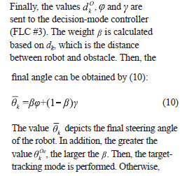
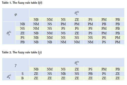
Regarding the fuzzy inference, the “and” was considered as a minimum operator. In other words, the linguistic rule was calculated through dot operator and minimum (min) operation [55]. Finally, the defuzzification process involved finding a physical value from these fuzzy sets. In this paper, the bisector was utilized to serve as a defuzzification operation [54]. The design process of the proposed scheme is demonstrated below. In Figure 2, the variables and serve as inputs of FLC #1, which may estimate the output variable of FLC #1 (rotation angle ) based on the position, current direction angle, target angle and final angle of the robot (the memberships of the input and output variables and the fuzzy rule table are shown in Figure 2 and Table 1, respectively.). Next, the input variable dk and are used for the obstacleavoidance controller (FLC #2) and for the calculation of the compensation angle , which can correct the moving path of the robot (the memberships of the input and output variables and the fuzzy rule table are shown in Figure 4 and Table 2, respectively.).
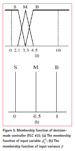
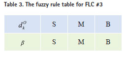
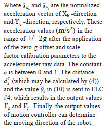
the obstacle avoidance mode is executed (again, the memberships of the input and output variables and fuzzy rule table for the obstacle avoidance controller are shown in Figure 5 and Table 3, respectively.). Next, the variables The value may be obtained through a landmark location map or dead reckoning algorithm (see the following section).
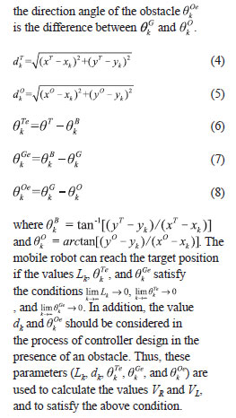
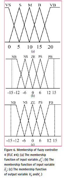
Dead reckoning A dead-reckoning algorithm can be used to calculate the location of a robot [56]. The odometer served as a displacement sensor for dead reckoning. A three-axis accelerometer and a singleaxis gyroscope were used to measure the static and dynamic tilt angles, respectively. Under this structure, the static location information for the robot was received by the GPS receiver and then the position of robot could be estimated through the sensor information from the odometer, gyroscope and accelerometer. The adoption of dead reckoning was performed through a reference point Pk (xk,yk) with the position known a priori in which the following position is determined by the following equations:
Table 4. The fuzzy rule table (VR).
References[1] M. Li, K. Imou, K. Wakabayashi, S. Yokoyama, “Review of research on agricultural vehicle autonomous guidance,” Int J Agric & Biol Eng, vol. 2, no. 3, pp. 1–16, 2009. [2] T. Hague, J. A. Marchant, N. D. Tillet, “Ground based sensing systems for autonomous agricultural robots,” Comput. Electron Agric., vol. 25, no. 1-2, pp. 11–28, 2000. [3] N. D. Tillett, “Automatic guidance sensors for agricultural field machines: a review,” J. Agric. Eng. Research, vol. 50, no. 33, pp. 167–187, 1991. [4] S. Gan-Mor, B. Ronen, S. Josef, Y. Bilanki, “Guidance of autonomous vehicle for greenhouse transportation,” Acta Hortic, no. 443, pp. 99–104, 1997. [5] J. F. Reid, Q. Zhang, N. Noguchi, M. Dickson, “Agricultural automatic guidance research in North America,” Comput. Electron. Agric., vol. 25, no. 1, pp. 155–167, 2000. [6] T. Bell, “Automatic tractor guidance using carrier-phase differential GPS,” Comput. Electron Agric., vol. 25, no. 1-2, pp. 53–66, 2000. [7] B. S. Blackmore, “Agricultural robot designs,” 2007. Data available from: http://www.unibots.com/ Agricultural_Robot_Designs.htm [8] A. Sánchez-Gimeno, J. Sánchez- Hermosilla, F. Rodríguez, M. Berenguer, J. L. Guzmán, “Selfpropelled vehicle for agricultural tasks in greenhouses,” Proceedings of the World Congress – Agricultural Engineering for A Better world, Bonn, Germany, 2006. [9] R. A. Tabile, E. P. Godoy, R. R. D. Pereira, G. T. Tangerino, A. J. V. Porto, R. Y. Inamasu, “Design and development of the architecture of an agricultural mobile robot,” Engenharia Agrícola, vol. 31 no. 1, pp. 130-142, 2011. [10] J. Sánchez-Hermosilla, R. González, F. Rodríguez, J. G.. Donaire, “Mechatronic Description of a laser autoguided vehicle for greenhouse operations,” Sensors (Basel), vol. 13, no. 1, pp. 769–784, 2013. [11] E. J. van Henten, J. Hemming, B. A. J. van Tuijl, J. G. Kornet, J. Meuleman, J. Bontsema, E. A. van Os, “An autonomous robot for harvesting cucumbers in greenhouses,” Autonomous Robots, vol. 13, no. 3, pp. 241-258, 2002. [12] S. Singh, T. F. Burks, W. S. Lee, “Autonomous robotic vehicle development for greenhouse spraying,” Transactions of the ASABE, vol. 48, no. 6, pp. 2355-2361, 2005 [13] P. J. Sammons, T. Furukawa, A. Bulgin, “Autonomous pesticide spraying robot for use in a greenhouse,” Australian Conference on Robotics and Automation, Sydney, Dec. 2005. [14] A. Stentz, “Robotic technologies for outdoor industrial robots,” Proc. SPIE, vol. 4374, pp. 192–199, 2001. [15] R. Siegwart, I. Nourbakhsh, Introduction to Autonomous Mobile Robots, MIT Press, April 2004. [16] N. Noguchi, H. Terao, “Path planning of an agricultural mobile robot by neural network and genetic algorithm,” Comput. Electron. Agric., vol. 18, no. 2-3, pp. 187–204, 1997. [17] A. Z. Abidine, B. C. Heidman, S. K. Upadhyaya, D. J. Hills, “Application of RTK GPS based auto-guidance system in agricultural production,” ASAE Annual International Meeting, MI, Paper No. O21152, 2002. [18] T. Schonberg , M. Ojala, J. Suomela, A. Torpo, A. Halme, “Positioning an autonomous off-road vehicle by using fused DGPS and inertial navigation,” International Journal of Systems Science, vol. 27, no. 8, pp. 745-752, 1996. [19] A. Stoll, H. D. Kutzbach, “Guidance of a forage harvester with GPS,” Precision Agriculture, no. 2, pp. 281–291, 2001. [20] A. Z. Abidine, B. C. Heidman, S. K. Upadhyaya, D. J. Hills, “Application of RTK GPS based auto-guidance system in agricultural production,” ASAE Paper no. O21152, ASAE, St. Joseph, MI, 2002. [21] R. E. Kalman, “A new approach to linear filtering and prediction problem,” Transaction on ASME: J. Basic Eng., no. 82, pp. 35–40, 1960. [22] B. Barshan, H. F. Durrant-Whyte, “Inertial navigation systems for mobile robots,” IEEE Transactions on Robotics and Automation, vol. 1, no. 3, pp. 328–342, 1995. [23] Y. Kubo, T. Kindo, A. Ito, S. Sugimoto, “DGPS/INS/wheel sensor integration for high-accuracy landrobot positioning,” Proceedings of 12th International Technical Meeting of the Satellite Division of the Institute of Navigation, pp. 555–564, 1999. [24] M. Norremark, H. W. Griepentrog, J. Nielsen, H. T. Sogaard, “The development and assessment of the accuracy of an autonomous GPS-based system for intra-row mechanical weed control in row crops,” Biosystems Engineering, vol. 101, no. 4, pp. 396–410, 2008. [25] J. O. C. Barawid, A. Mizushima, K. Ishii, N. Noguchi, “Development of an autonomous navigation system using a two-dimensional laser scanner in an orchard application,” Biosystems Engineering, vol. 96, no. 2, pp. 139–149, 2007. [26] L. A. Zadeh, Fuzzy Sets. Info. and Control, vol. 8, no. 3, pp. 338–353, 1965. [27] L. A. Zadeh, “A rationale for fuzzy control,” J. Dyn. Syst.-T. ASME, vol. 94, no. G, pp. 3-4, 1972. [28] D. A. Waterman, A Guide to Expert Systems, Addison-Wesley Longman Publishing, Boston, 1986. [29] M. Fasanghari, G. A. Montazer, “Design and implementation of fuzzy expert system for Tehran Stock Exchange portfolio recommendation,” Expert Syst. Appl., vol. 37, no. 9, pp. 6138–6147, 2010. [30] S. Kolhe, R. Kamal, H. S. Saini, G. K. Gupta, “An intelligent multimedia interface for fuzzy-logic based inference in crops,” Expert Syst. Appl., vol. 38, no. 12, pp. 14592-14601, 2011. [31] T. T. Lee, W. J. Wang, “Design of a multi-layer fuzzy logic controller for multi-input, multi-output systems,” Fuzzy Set Syst., vol. 111, no. 2, pp. 199–214, 2000. [32] Y. H. Kuo, J. P. Hsu, C. W. Wang, “A parallel fuzzy inference model with distributed prediction scheme for reinforcement learning,” IEEE Trans. Syst, Man Cyber., vol. 28, no. 2, pp. 160-172, 1998. [33] V. M. Peri, D. Simon, “Fuzzy Logic Controller for an Autonomous Robot,” North American Fuzzy Information Processing Society Conference (NAFIPS 2005), pp. 337-342, June 2005. [34] D. K. Chwa, “Sliding-mode tracking control of nonholonomic wheeled mobile robots in polar coordinates,” IEEE Transactions on Control Systems Technology, vol. 12, no. 4, pp. 637-644, 2004. [35] J. M. Yang and J. H. Kim, “Sliding mode control for trajectory tracking of nonholonomic wheeled mobile robots,” IEEE Transactions on Robotics and Automation, vol. 15, no. 3, pp. 578-587, 1999. [36] G. C. Antonelli, S. G. Fusco, “A fuzzylogic- based approach for mobile robot path tracking,” IEEE Trans. on Systems, Man and Cybernetics: Systems and Humans, pp. 211-221, 2007. [37] T. Das, I. Kar, “Design and implementation of an adaptive fuzzy logic-based controller for wheeled mobile robots,” IEEE Trans. on Control Systems Technology, vol. 14, no. 3, pp. 501-510, 2006. [38] S. M. Raguraman, D. Tamilselvi, N. Shivakumar, “Mobile robot navigation using Fuzzy logic controller,” International Conference on Control, Automation, Communication and Energy Conservation, pp. 1-5, June 2009 [39] H. Boubertakh, M. Tadjine, P. Y. Glorennec, “A new mobile robot navigation method using fuzzy logic and a modified Q-learning algorithm,” Journal of Intelligent and Fuzzy Systems, vol. 21, no. 1-2, 2010. [40] B. Lacevic, J. Velagic, “Evolutionary design of fuzzy logic based position controller for mobile robot,” Journal of Intelligent and Robotic Systems, vol. 63, no. 3-4, pp. 595-614, 2011. [41] U. Farooq, K. M. Hasan, M. U. Asad, S. O. Saleh, “Fuzzy logic based wall tracking controller for mobile robot navigation,” 7th IEEE conference on Industrial Electronics and Applications (ICIEA), pp. 2102-2105, July 2012. [42] L. C. Hung, H. Y. Chung, “Design of hierarchical fuzzy logic control for mobile robot system,” IEEE Robotics, Automation and Mechatronics Conference, pp. 1-6, Bangkok, Dec. 2006. [43] E. J. van Henten, J. Hemming, B. A. J. van Tuijl, J. G. Kornet, J. Meuleman, J. Bontsema, E. A., van Os, “An autonomous robot for harvesting cucumbers in greenhouses,” Autonomous Robots, vol. 13, no. 3, pp. 241–258, 2002. [44] D. M. Bulanon, T. Kataoka, H. Ukamoto, S. Hata, “Development of a real-time machine vision system for the apple harvesting robot,” SICE Annual Conference, vol. 1, pp. 595-598, Sapporo., Japan, 2004. [45] N. Correll, N. Arechiga, A. Bolger, M. Bollini, B. Charrow, et al., “Building a distributed robot garden,” Proc. of the IEEE/RSJ Intl. Conf. on Intelligent Robots and Systems (IROS), 1509-1516, 2009. [46] C. L. Chang, B. H. Wu, C. C. Chang, “Autonomous field robotic robot with embedded multi-sensor system for agricultural applications,” ION International Technical Meeting (ION ITM), pp. 1077–1084, 2011. [47] Li Y, M. Efatmaneshnik, A. G. Andrew, “Attitude determination by integration of MEMS inertial sensors and GPS for autonomous agriculture applications,” GPS Solutions, vol. 16, no. 1, pp. 41–52, 2012. [48] C. M. Gifford, R. Webb, J. Bley, D. Leung, M. Calnon, J. Makarewicz, B. Banz, A. Agah, “A novel lowcost, limited-resource approach to autonomous multi-robot exploration and mapping,” Journal Robotics and Autonomous System, vol. 58, no. 2, pp. 186-202, 2010. [49] J. Borenstein, “Experimental results from internal odometry error correction with the OmniMate mobile platform,” IEEE Trans. Robotics and Automation, vol. 14, no. 6, pp. 963–969, 1996. [50] V. Subramanian, T. F. Burks, A. A. Arroyo, “Development of machine vision and laser radar based autonomous robot guidance systems for citrus grove navigation,” Comput. Electron. Agric., vol. 53, no. 2, pp. 130–143, 2006. [51] B. H. Wu, C. L. Chang, “Application of neuro-fuzzy system to agricultural vehicle for local map construction and navigation,” International Symposium on Machinery and Mechatronics for Agricultural and Biosystems Engineering (ISMAB), C2-17, pp. 341– 346, Jeonju, Koera, June 18-20, 2012. [52] E. Benson, T. Stombaugh, N. Noguchi, J. Will, J. F. Reid, “An evaluation of a geomagnetic direction sensor for robot guidance in precision agriculture applications,” ASAE Annual International Meeting, Paper no. 983203, 1998. [53] G. Dudek, M. Jenkin, Computational Principles of Mobile Robotics, Cambridge University Press, 2000. [54] C. C. Lee, “Fuzzy logic in control system: Fuzzy logic controller, part I and II,” IEEE Trans. System, Man and Cyb., vol. 20, no. 2, pp. 404–435, 1990. [55] R. J. Marks, Fuzzy Logic Technology and Applications, IEEE Technology Update Series, pp. 19–24, 1994. [56] G. V. zur Bonsen, D. Ammann, M. Ammann, E. Favey, P. Flammant, “Continuous navigation: combining GPS with sensor-based dead reckoning,” GPS World, vol. 16, no. 4, pp. 47-54, 2005. The concluding part of the paper will be published in the next issue where the hardware and software design process and experimental results, including performance analysis and a comparison of different type of navigation methods will be discussed. |


 (16 votes, average: 4.25 out of 5)


Good work.
Leave your response!