| GNSS | |
Outcomes of SBAS-Africa project
Feasibility analysis, infrastructure development, aviation, precision agriculture, UAV, maritime demonstration trials and preliminary business case for a South African SBAS |
|
|
|
|
|
|
|
Whilst Europe has benefitted for a number of years from the European Geostationary Navigation Overlay Service (EGNOS) and North America from the Wide Area Augmentation Service (WAAS), the countries of Africa have not had the same opportunity to benefit both economically and socially from improved navigation services. Many airports across Africa lack the infrastructure that enables aircraft to use precision landing approaches. This makes landings less safe, reduces their mainstream commercial use and constrains regional economic development.
One of the top priorities of the Africa- European Union cooperation is the Satellite Based Augmentation Service (SBAS) introduction in Africa aiming to support Air Transport Sector and Satellite Navigation. After several meetings remarking the third Africa-EU Summit, an action plan for the years 2011-2013 was agreed to implement the Joint Africa EU strategy. The expected result was to build a core technical capacity for SBAS within relevant African organizations in each region and to implement the preliminary backbone infrastructure.
The SBAS-Africa project (http://sbasafrica. avantiplc.com/) – led by Avanti Communications plc (Avanti) and co-funded by the UK Space Agency (UKSA) under the International Partnership Space Programme (IPSP) has been made possible by a collaboration between the South African National Space Agency (SANSA) and the UK Space Agency (UKSA). The objectives for this programme are to promote and foster the international relationship and to bring societal or economic benefits from the use of satellite or space technology for countries that currently do not have these benefits.
In partnership with GMV, NSL, Pildo Labs, TAS UK, the South African National Space Agency (SANSA), Ghana Council for Scientific and Industrial Research and the Agency for Aerial Navigation Safety in Africa and Madagascar (ASECNA), the SBAS-Africa project has delivered a live SBAS signal in space serving the southern part of the African continent. The system generates SBAS messages using GMV’s magicSBAS tool suite with input data from a network of GPS ground monitoring stations developed by NSL which are deployed across South Africa and neighbouring countries. The messages are broadcast via the ARTEMIS satellite originally an ESA EGNOS test satellite which is now owned and operated by Avanti plc. The system provides an immediate improvement of GPS accuracy having far-reaching benefits across a range of user communities and applications, such as aircraft precision landings.
The impact of SBAS-Africa will be the acceleration in the adoption of Satellite Based Augmentation Services (SBAS) within Africa for the benefit of African aviation safety and the wider African economy. As a flagship project SBAS-Africa paves to way towards an operational SBAS service which brings benefits to many market sectors including maritime navigation, precision agriculture and general aviation. Apart from economic benefits, it will stimulate innovation, attract inward investment, create high-value jobs, reduce imports and open up new export markets, increase productivity and improve the environment among others.
For African partners, this project represents an opportunity to understand the safety, societal and economic benefits that SBAS services will offer, to build business cases for and to move towards a fully operational SBAS service.
SBAS-Africa context
As explained above, the SBAS-Africa project [1] – led by Avanti Communications PLC (Avanti) and co-funded by the UK Space Agency (UKSA) under the International Partnership Space Programme (IPSP) has been made possible by a collaboration between the South African National Space Agency (SANSA) and the UK Space Agency (UKSA). The objectives for this programme are to promote and foster international relationships and to bring societal or economic benefits from the use of satellite or space technology for countries that currently do not have these benefits.
In partnership with GMV, NSL, Pildo Labs, TAS UK, the South African National Space Agency (SANSA), Ghana Council for Scientific and Industrial Research and the Agency for Aerial Navigation Safety in Africa and Madagascar (ASECNA), the SBAS-Africa project generated a live SBAS signal in space serving the southern part of the African continent and delivered:
• 1-metre horizontal accuracy SBAS test services for Southern and Eastern Africa
• Service demonstration and user trials for aviation, maritime and agriculture sectors
• A draft capital project appraisal and transition plan for SBAS in South Africa
• A basis for extension to southern African neighbouring states and build-up of capacity in region
This paper provides an overview of the system infrastructure and of the performances achieved during the demonstration campaign. It also showcases the results of the business case for a South African SBAS.
SBAS-Africa infrastructure
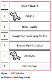
The end to end infrastructure can be divided in 7 parts (see Figure 1): a network of GNSS Ground Monitoring Stations (GMS) deployed in Southern Africa, the HYLAS 2 Avanti satellite to transmit the GPS data collected by the GMS monitoring stations, the NTRIP caster, GMV’s magicSBAS [2] Processing Facility that computes the SBAS messages and the Ground Uplink Station (GUS) that sends the messages to ARTEMIS satellite which then broadcasts them throughout its area of coverage on the L1 GPS frequency to the users.
The Ground Monitoring Stations (GMSs) are generally deployed throughout the area where the SBAS corrections will be valid. In the case of SBAS-Africa, they are spread throughout the whole country of South Africa. The GMSs collect the navigation information from the GPS satellites they have in view and send it to the NTRIP caster. The monitoring stations consist of the three following element:
• A dual frequency GPS antenna
• A GPS receiver to receive dual frequency GPS raw messages
• A VSAT to transmit the raw GPS message in a timely manner to the magicSBAS SBAS processing facility. The messages need to be received by the processing facility in less than 1 second.
The high throughput Avanti satellite HYLAS 2 is used to send the GPS raw messages to the magicSBAS SBAS Processing Facility in a timely and highly-reliable manner. If the navigation messages were not received on time by the magicSBAS Processing Facility, they would be discarded and the SBAS messages would not contain such information. If that situation persists for a long time and for the whole network of stations, the SBAS messages generated would lack of valid SBAS corrections data. Also, since the GMSs are mostly located in remote locations with little or no means of reliable access to internet, relaying data through satellite often represents the only way to ensures reliable and timely delivery of GPS messages to compute the SBAS corrections.
The Networked Transport of RTCM via Internet Protocol (NTRIP) caster is a software hosted on a server in the Avanti Goonhilly (GHY) data centre in the UK. This programme receives the raw GPS messages from all the GMSs deployed and acts as a server to access the data from a centralised, time-synchronised source. The data is also recorded on the server for research purposes.
The SBAS messages are generated by magicSBAS, a state-of-theart, multi-constellation, operational SBAS testbed developed by GMV to offer regional differential corrections and non-safety critical integrity augmentation to any interested region.
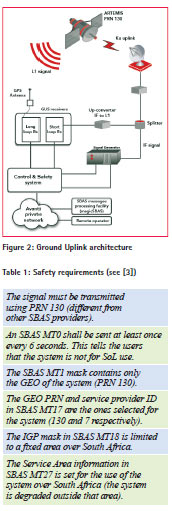
The Ground uplink station (see Figure 2) comprises a first part which included the signal generator and the control and safety system and a second part that enables the transmission to ARTEMIS (up-converter, High Power Amplifier and Antenna). The Avanti ground uplink station is located in the Makarios Satellite Earth Station in Cyprus. The SBAS messages are uplinked to ARTEMIS in Ku-band using a 4.9m dish antenna.
The ARTEMIS GEO satellite previously owned by ESA and now property of Avanti Communications was originally used operationally as part the EGNOS constellation to provide Safety of Life services from 2011 through 2013. For SBAS-Africa ARTEMIS GEO was used to broadcast the signal on GPS PRN130 and allowed multiple user trials to be performed.
Safety and interoperability
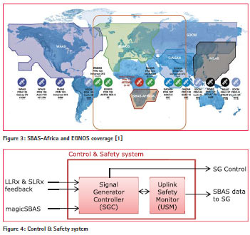
SBAS-Africa intends to implement a testbed, precursor of an operational SBAS system for non-safety-of-life users. However, SBAS-Africa copes with a challenge that neither WAAS nor EGNOS had: SBAS-Africa shares GEO coverage with already mature Safetyof- Life (SoL) SBAS providers. These providers are mainly EGNOS, to a lesser extent WAAS and the recently certified one, GAGAN in India (see Figure 3).
The shared GEO coverage with other SBAS providers implies the necessity of introducing strict safety protections in the SBAS-Africa architecture, with a level of assurance comparable to that of WAAS or EGNOS itself.
To implement such a level of safety, a rigorous safety analysis was carried out, detecting the possible ways in which SBAS-Africa could affect other SBAS service performance or impact their users. Another critical aspect is that SBAS-Africa must inform its users that the signal may only be used for non- SoL operations. A user, for instance an aircraft, could be coming from a SBAS SoL enabled area, like Europe and start using the SBAS-Africa signal as if it were SoL. Taking these two factors into account, the minimum safety requirements in Table 1 were obtained.
The SBAS-Africa project was constrained to develop the SBAS prototype system with a limited cost (much lower than WAAS or EGNOS prototypes) and also in a short period of time (less than a year). In order to overcome this challenge, a novel approach was envisaged. This approach consisted on dividing the uplink system in two hardware/software processing elements: the Signal Generator Controller (SGC) developed with a non-critical assurance standard and the Uplink Safety Monitor (USM), developed with high assurance standards. All safety-critical checks are to be performed by the USM ensuring that the requirements in Table 1 are met, even if the rest of the system failed. Figure 4 shows the SGC and USM within the Control and Safety system.
As it can be seen in Figure 4 the SGC acts as a communications hub: it receives the SBAS messages to be broadcast from the magicSBAS [2] server and also serves as an interface with the operator. The SGC is also in charge of collecting the feedback data from the Long and Short Loop Receivers (the first one receiving signalin- space and the second one connected to the Signal Generator output directly) as well as commanding the Signal Generator and sending the SBAS messages and feedback from the receivers to the USM.
The USM has been designed to work autonomously i.e. it is not commanded, it is not connected to the internet and its configuration is hardcoded. This element checks the PRN using the feedback from the receivers and analyses the SBAS messages before sending them to the Signal Generator and being broadcast. It checks also the consistency between the messages sent and the ones received through the receivers, detecting any possible anomaly after the message is sent to the Signal Generator. Note that the SBAS messages have to go through the USM to get to the Signal Generator; therefore it is a physical barrier. The USM will enable the signal generation only if all the safety checks pass.
System performance
SBAS performance is typically measured by the following concepts:
• Accuracy: measurement of how small position error is. At user level it is a statistical distribution of error, while at system level it uses estimated range errors and geometry.
• Integrity: measure of trust on the correctness of the service. ‘Protection levels’ can be defined as statistical bounds on the position error for a target integrity risk of 10-7 following aviation standards. See [4].
• Availability: this is the fraction of time that the computed protection levels are below a threshold known as ‘Alert Limit’.
• Continuity: measurement of the probability that the system becomes unavailable during a certain procedure (for example, a precision approach).
System level
The performance at system level can be measured by GMV’s ECLAYR [5] tool. From the two-week series of trials the performances from 14th March have been selected as example (performance is similar throughout the trials period). The figures show the results for that day.
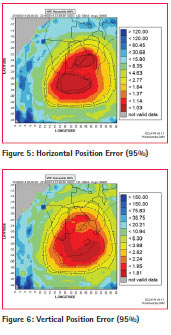
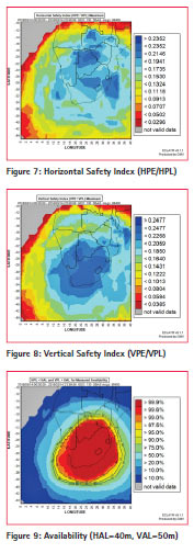
Figure 5 and Figure 6 show that the system accuracy, defined by the 95th percentile of position error, is typically about one meter horizontally and below two meters vertically over South Africa.
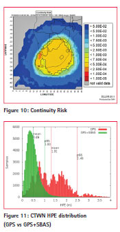
As a measurement of integrity, the Safety Index can be defined as the quotient between position error and protection level (horizontally and vertically). When the SI is below one, then the system preserves integrity. Figure 7 and Figure 8 show that for a typical day, the maximum safety index is below 0.25 for any location within the service area, which means that the position error is four times smaller than the protection level.
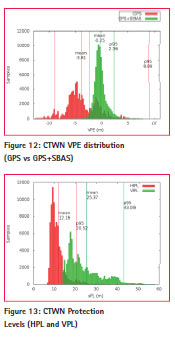
The availability at APV-I service, defined by a horizontal alert limit of 40m and vertical alert limit of 50m is plotted in Figure 9. As it may be observed, the availability is above 99.9% over South Africa. Continuity risk at this level is below 5·10-4.
User level
In addition to the results at system level presented in the previous subsection, performance can also be measured at user level.
GMV’s magicGEMINI [6] tool can be used to compute performance using GNSS data – either real-time or stored GNSS data, with the possibility to compute several solutions simultaneously.
As an example, data obtained from the Cape Town Trignet station CTWN can be analysed (for 24 hours on the 13th March). The SBAS-aided solution can therefore be compared to the standalone- GPS solution. Figure 11 and Figure 12 show the statistical distributions of horizontal and vertical position error, respectively. The GPS-only distribution is plotted in red, and the SBAS-aided solution in green. Percentile 95 is computed from absolute value of error.
Although Cape Town is not a central location in the service area (as it can be observed in Figure 5 and Figure 6), the performance obtained by SBAS-Africa in this station has an accuracy of 1.00m (95%) horizontally and 2.35m (95%) vertically, which is comparable to WAAS or EGNOS.
Computed statistics show that mean protection levels during the same period are 12.2m and 25.4m for the horizontal (red) and vertical (green) components, respectively.
Trials
Flight trials
In the case of aviation, the International Civil Aviation Organisation (ICAO) has developed the Approach with Vertical guidance (APV) concept. An SBAS APV is an approach similar to an ILS (Instrument Landing System) approach, i.e. it comprises, essentially, a localisation segment to orient the aircraft on final approach with a continuous descent profile to the landing area. It is implemented as a specific Localiser Performance with Vertical (LPV) guidance approach. Operationally, it is flown in precisely the same way as an ILS approach and has similar performance. SBAS technology can also be used to fly Point-in-Space (PinS) approaches for rotorcraft, where similar concepts are employed to enable localization onto a point in space followed by a visual approach to the helicopter landing area. The benefits of SBAS in aviation are very well-known and include, amongst others, decision height minima reduction, safety enhancement via vertical guidance which reduces the risk of controlled flight into terrain (CFIT), and more flexibility in procedure implementation. The objectives of the trials were to demonstrate the benefits that an SBAS service can provide to Southern African aviation stakeholders.
A series of aviation trials were performed by PildoLabs Wessex using their portable flight validation and inspection platform known as PLATERO. PildoLabs designed and developed a set of test approach/departure procedures to enable the demonstration of the SBAS-supported test flights. As noted above (see section III) since the SBASAfrica signal was broadcast in test mode with message type MT0 transmitted every six seconds, certified aviation equipment could not use the signal as is. Therefore, in order to be able to fly SBAS procedures using the SBAS messages generated by magicSBAS and provided by the ARTEMIS GEO satellite, PLATERO was adapted to decode and process the SBAS test signal. PLATERO provides the pilots with flight guidance via standard flight instrumentation for navigation and guidance.
The flight trials campaign, based on Lanseria International Airport (ICAO: FALA) in South Africa and utilizing the live, real-time SBAS-Africa signal in space during March and April 2016, comprised the following:
• SBAS LPV approach to Lanseria International Airport (instrument flight rules – IFR – airport)
• SBAS LPV approach to Grand Central Airport (visual flight rules – VFR – airport)
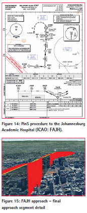
• SBAS PinS approach to Charlotte Maxeke Johannesburg Academic Hospital
• SBAS low-level helicopter route connecting Lanseria International Airport with Johannesburg Academic Hospital
Two South African air operators, namely MCC Aviation (fixed-wing) and HALO Aviation (rotorcraft) have been involved in these demonstrations, providing aircraft, flight crews and facilitation in the air traffic environment. Below, we provide an extract of the information pertaining to the rotorcraft trials.
Additionally, a set of flight trials (fixedwing) were conducted by Pildo Labs (in conjunction with Thales Alenia Space and ASECNA) at Amborovy Airport (ICAO: FMNM), Madagascar, where LPV-like approach procedures were flown using GPS only and by applying the SBAS solution computed in a post-processed data mode. The intention of these trials was to demonstrate the expandability of the SBAS-Africa service coverage over Madagascar. Sky Services Mahajanga provided the aircraft and aircrew to enable the flight trials to take place.
Overall, the trials demonstrated the utility of SBAS technology in the aviation sector:
• The test LPV minimum obtained on Lanseria runway RWY07 due to SBAS is 300ft which is similar to ILS CAT-I and 400 feet lower than the LNAV (GPS-only) minimum. As such, the usual SBAS benefits of increased capacity, operability and utility for the airport would apply.
• In the case of a non-IFR airports such as Grand Central, the demonstrated SBAS capability provides an opportunity to improve capacity whilst keeping the costs at manageable levels. Even if, under current regulations, it is not possible to implement IFR procedures at Grand Central, SBASAfrica has demonstrated that SBAS could provide the airport with an LPV-like approach procedure with a minimum of 410 feet onto RWY17.
• For rotorcraft, SBAS enables safer approach procedures due to the horizontal and vertical guidance provided, and due to better accuracy and integrity. In the case of Johannesburg Academic Hospital, the PinS procedure designed to the final approach and take-off (FATO) area would allow an instrument approach down to a minimum of 540 feet with SBAS (whereas with GPS-only it would be 1080 feet).
The feedback from all pilots was positive and supportive of the system. As an example, a pilot from Sky Service operating in Madagascar commented: “I think SBAS presents a great advantage for airports where weather conditions can be variable and violent, since it allows secured precision approaches without any specific ground installations”.
Drone trials
The drone trials were carried out by NSL and supported by Haevic. NSL provided and operated the GNSS equipment, processing the data and analysing results. Haevic provided and operated the vehicles, arranged the test flights, prepared the drones for the additional equipment and provided market expertise. Trials were performed between the dates of 9-16 March 2016 using three different drones at different locations; Potschefstroom and Klerksdorp in North West Province and Koekenaap in the Western Cape province of South Africa. Different types of GNSS receiver were used during the trials, each offering a different accuracy and therefore being used for a different objective.
SBAS Receiver
Many different GNSS receivers are capable of receiving, decoding the SBAS messages and implementing the ionospheric, orbit and clock corrections within their navigation solution. The purpose of this receiver was to be able to provide a navigation solution for drones, offer survey grade positioning and to store raw measurement data for post-processing. SBAS is only on the GPS L1 signal and therefore the basic functionality of the receiver had to be single frequency L1.
The SBAS-Africa SBAS signal in test mode is that in which Message type 0 is transmitted for SBAS testing. After the reception of message type 0, all ranging and correction information obtained from the SBAS must be discarded for safety critical applications. The existence of a message type 0 indicates that the system integrity performances are not assured. Another requirement was that the receiver could operate with Message Type 0.
The EOS Arrow series of receiver was selected as the SBAS receiver and the “100 Subfoot GNSS” model was purchased.
Real Time Kinematic GNSS Receiver
It was necessary to provide the possibility to determine high accuracy positioning of the drone flights in order to determine the accuracy of the SBAS system. It was decided that the single frequency RTK processing would suffice for this purpose and it was preferred that the processing was on-board.
To perform RTK positioning a GNSS receiver at a fixed base/reference station is necessary and this needs to be within a few (< 5km) of the roving receiver. The two receivers need to be connected via a radio data link. Due to problems that can occur with the data link, the receivers also need to log data allowing the possibility of post-event post-processing.
The additional requirement for the receiver was to be small weight and power in order to be installed on a drone. The Emlid Reach GNSS receiver was selected and an evaluation kit purchased. The Reach is a uBlox-based GNSS receiver and is designed for the drone market.
Professional Grade GNSS Receiver
In order to provide positioning within a geodetic reference frame, a professional grade GNSS receiver was also required. This is used at the fixed base/reference stations and the data that is collected is processed with data from local Continuously Operating Reference Stations (CORS) within South Africa as part of the Trignet network of CORS.
This receiver needed to be multifrequency (minimum triple) and constellation, be able to record and store local to the device and to have an internal battery as power would not be available in the field.
The Comnav 300 Pro was chosen as the reference station.
Test 1
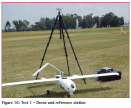
Three different drone flight trials were carried out, two with fixed wing vehicles and the other with a rotor style drone. In additional, a static test was performed during the drone test period. Test 1 utilized the Haevic 1 drone flown along an agricultural flight path from Potchefstroom model aircraft club. Haevic 1 is a foam aero frame fixed wing drone with a 2.06m wingspan with the capability of flying for around 45 minutes. Its main use of operation is for aerial surveying, safety and security and reconnaissance.
The Arrow 100 and the Reach were installed within the fuselage with a single antenna feeding both receivers via a two way splitter. A reference station was established adjacent to the runway with the antennas mounted on a tripod. The Comnav and Reach were used for reference stations. The two Reach receivers communicated via 868MHz radio.
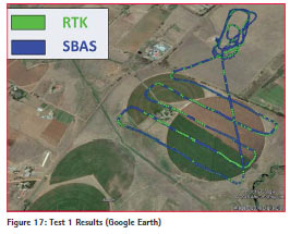
The drone was flown for two separate flights with the Arrow and Reach recording the SBAS and RTK positioning respectively. The Reach was tied into the local realization of WGS84 through processing the Comnav (common reference site) with Trignet data.
The results for Test 1 are shown in Figure 17. The standalone GPS is equivalent to a normal user’s GPS position. Only resolved ambiguity RTK has been used.
Test 2
Test 2 used a larger drone known as a Panga 3M. This is a larger vehicle than the Haevic 1 with a 3m wingspan and a flight duration of up to 3 hours. The drone has a large volume fuselage being capable of carrying payloads up to 15kg. Again, the drone is used for aerial survey, safety and security applications and reconnaissance.
Being a large size drone, this requires an airport take-off and landing and the test was flown from Klerksdorp airport. The Arrow 100 and the Reach were installed within the fuselage with a single antenna feeding both receivers via a two way splitter. A reference station was established adjacent to the runway with the antennas mounted on a tripod. The Comnav and Reach were used for reference stations. The two Reach receivers communicated via 868MHz radio. Results were similar to test 1.
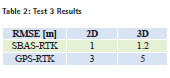
Test 3
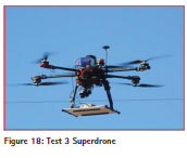
Test 3 used the Haevic Superdrone rotor style drone. This is a carbon fibre airframe with a small payload capability and is usually flown for survey, inspection, safety and security. A windfarm inspection flight path was flown with the Arrow 100 and the Reach installed on the baseplate with a single antenna feeding both receivers via a two way splitter. A reference station was established near to the surveyed structure with the antennas mounted on a concrete base.
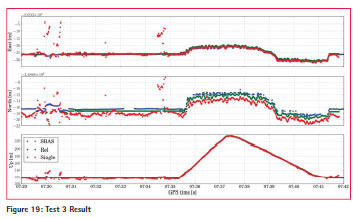
The results are shown in Figure 19 (red standalone GPS, blue SBAS, green RTK) and Table 2 showing SBAS producing a 2D accuracy of ~1m against standalone GPS of ~3m. The stability of the SBAS position against both the RTK and GPS positions is also clearly apparent.
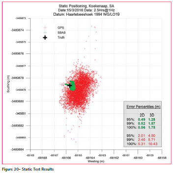
Static Test
As well as testing the SBAS performance on the drones, the opportunity was taken to use the equipment for static tests. Here the Arrow, Reach and Comnav were set up to record data for a two and a half hour period on a static field location. A single antenna was used with a three way antenna splitter.
The Comnav was used to determine the precise location of the antenna and was processed as a network solution against two Trignet stations. The Reach was used for standalone GPS positions and the Arrow for the SBAS positions. In total, approximately 9000 epochs, or data points were collected by each receiver. The results are shown in Figure 20 which clearly demonstrates the improvement of the SBAS-Africa solution over standalone GPS. Within this data sample, the SBAS results are producing a 95% horizontal accuracy of less than half of a metre. Standalone GPS is at the two metre level. When looking at 3D results, SBAS-Africa gives a 95% accuracy of 1.3m against standalone GPS of 4.5m.
Agriculture trials
In Europe, EGNOS is extensively used by the agriculture sector providing high precision at low cost and therefore enabling the use of precision agriculture techniques.
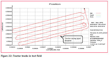
The use of tractor guidance was demonstrated using the SBAS signal generated by the team. The trials were executed in a test field owned by the University of Stellenbosch in South Africa.
The GNSS equipment chosen was standard commercially available units that farmers would commonly use in precision farming situations.
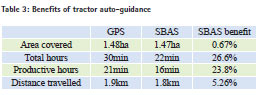
The results of the trials show that increased accuracy provided by the SBAS signal could be used to use auto guidance on tractors in South Africa.
A reduction in distance of 5.25% was observed with an increase in overall productivity of 26.6% using SBAS.
GPS positional accuracy is not good enough for accurate precision applications but the increased accuracy with SBAS enables precision agriculture system such as tractor guidance technology which brings numerous benefits. For example, it reduces overlap in the application of agricultural chemicals, reduces field traffic and compaction; it also reduces operator fatigue. It enables Variable Rate Technology (VRT) to deliver precise application of plant protection products across any type of field, all of this resulting in an improvement of crop yields.
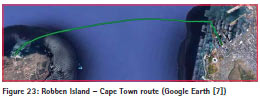
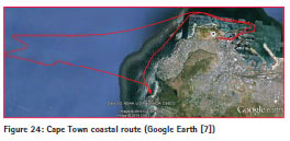
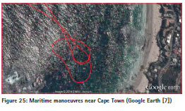
Maritime trials
For the SBAS trials in maritime applications, several tests were performed on board the Cape Town to Robben Island regular ferries (Figure 23), in addition to a custom route near Cape Town in which several manoeuvres were tested (Figure 24, Figure 25). These trials tested the ability to compute an SBAS-aided solution at sea, which implies several restrictions with respect to a static receiver such as the one considered in section IV.B:
• Interference and multipath from other equipment on board.
• Reduced satellite visibility due to antenna placement and wave motion.
• Degraded SBAS performance as distance to the coast increases.
The first of these points was particularly concerning since it required careful placement and a relatively highquality GNSS antenna. The third point was not tested since it was not possible to be far enough from the coast to notice the degradation.
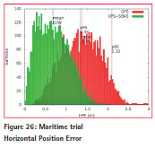
In order to compute accuracy statistics, GMV’s magicPPP [8] was used to postprocess the receiver dual-frequency observations and obtain a PPP trajectory, which can in turn be used as a reference position in order to compare standalone GPS and SBAS-aided solutions with magicGEMINI [6]. This can be done thanks to PPP’s centimetre-level accuracy. Applying this method to a Robben Island to Cape Town journey on the 8th April, the obtained horizontal accuracy results are shown in Figure 26. As it may be observed, mean horizontal position error in the SBAS-aided position is 0.69m, which is an improvement over the GPSonly case (1.36m). When comparing to the results in section IV.B, it must be noted that in this case the reference trajectory cannot be known to such a high degree as in the case of a static location and that the position is affected by the specific maritime circumstances, as explained above. The results are nevertheless in line with the expected behaviour, showing a horizontal accuracy improvement of about 40% over the 73 minutes analysed

Business case
The RSA SBAS vision is for an affordable, government-funded SBAS service for public good that is free of direct user charges and delivers a high return on investment from downstream user and policy delivery benefits.
A preliminary SBAS business case has been produced in accordance with RSA National Treasury’s capital planning guidelines [9]. It comprises a qualitative policy delivery assessment based on policy objectives as well as a quantified costbenefit analysis (CBA) based on system costs and downstream user benefits.
The qualitative policy delivery assessment has considered a set of initial policy drivers arising from the RSA National Planning Commission’s National Development Plan [10] and the President’s Nine-Point Plan [11] as well as seven departments’ strategic plans [12] [13] [14] [15] [16] [17] [18].
The assessment shows that SBAS can support RSA policy delivery across a range of areas including: compliance monitoring and enforcement; education; the environment; productivity; industrial capacity; jobs; reducing inequality; improving safety; and stimulating innovation.
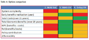
The quantified CBA has considered four options:
1. Do Nothing – No further SBAS activity but greater reliance on existing public and commercial augmented GPS services.
2. SBAS Safety-of-Life (SoL) for the South African Development Community (SADC) based on EGNOS or WAAS technology.
3. SBAS Open Service (OS) based on SBAS-Africa technology enhanced to deliver general aviation benefits and extended across the SADC.
4. Delayed SBAS OS (by seven years) for SADC based on SBAS-Africa technology.
The preferred Option 3 (SBAS OS) delivers over ZAR 15.6 billion (discounted) to the RSA economy over 25 years with a return on investment greater than 10:1. The RSA SBAS can also be extended to deliver major economic benefits to SADC countries.
A high-level risk assessment has been carried out together with a sensitivity analysis to establish an action plan and clarify the strength of the quantitative analysis.
Table 4 summarises the different options. It concludes that Option 3 (SBAS OS) is the best option for the foreseeable future in terms of total economic benefits, timing, cost, net present value, return on investment, risk and feasibility.
Conclusion
The SBAS-Africa consortium implemented a full end-to-end SBAS test bed with the generation of a live, realtime SBAS signal over South Africa via a space-borne navigation transponder aboard ARTEMIS within a year.
During the course of the project, a series of trials and demonstrations were executed in key market sectors including aviation, maritime and precision agriculture in order to validate the infrastructure deployed. SBAS was also tested for the use of drones. Every user came to the conclusion that an SBAS would bring benefits to their fields. In parallel to the technical implementation of the system, an investment appraisal and business case according to RSA Treasury guidelines was developed showing and ROI of 10-to-1 and an economic impact of ZAR 1.5 billion per annum. The work accomplished establishes a basis for SBAS services development in Southern Africa, including South Africa, Madagascar and other SADC member states and giving all the elements to move towards a fully operational cost effective SBAS service.
Acknowledgments
The SBAS-Africa consortium would like to acknowledge MCC, Halo, LANSERIA International Airport, Grand Central Airport, Haevic, Precision Decision, University of Stellenbosch, SAMSA, TRANSNET, Robben Island Museum, Tigger2Charters, Marine Data Solutions, NGI, SANSA and IGS for their support to organize the trials and workshops throughout South Africa.
References
[1] Avanti, “SBAS-Africa,” [Online]. Available: http:// sbas-africa.avantiplc.com.
[2] GMV, “magicSBAS,” [Online]. Available: http://www.gmv.com/en/ space/magicSBAS/index.html.
[3] RTCA, DO-229D Minimum Operational Performance Standards for Global Positioning System Airborne Equipment, 2006.
[4] ICAO, International Standards and Recommended Practices; Annex 10 to the Convention on International Civil Aviation; Aeronautical Telecommunications, Vol. I Radio Navigation Aids; 6th Ed., 2006.
[5] GMV, “ECLAYR,” [Online]. Available: http://www.gmv.com/ en/space/products/eclayr/.
[6] GMV, “magicGEMINI,” [Online]. Available: http://www.gmv.com/en/ aeronautics/products/magicGEMINI.
[7] Google, “Google Earth,” [Online]. Available: http://www.google.com/earth/.
[8] GMV, “magicPPP,” [Online]. Available: http://www.gmv.com/ en/space/magicPPP/index.html.
[9] RSA National Treasury (2015) 2016, “Capital Planning Guidelines,” 2015. [Online]. Available: http://www. treasury.gov.za/publications/guidelines/ Capital%20Planning%20Guidelines%20 2016.pdf. [Accessed 14 December 2015].
[10] RSA National Planning Commission, “National Development Plan 2030: Our Future – Make it Work. Executive Summary.,” 2012. [Online]. Available: http://www.gov.za/sites/www.gov. za/files/Executive%20Summary- NDP%202030%20-%20Our%20 future%20-%20make%20it%20work. pdf. [Accessed 27 January 2016].
[11] RSA Government (2015), “Nine- Point Plan.,” [Online]. Available: http://www.gov.za/node/746702. [Accessed 4 March 2016].
[12] RSA Department for Agriculture, Forestry and Fisheries (2015), “Strategic Plan 2015/16 – 2019/20.,” [Online]. Available: http://www.daff.gov.za/doaDev/ topMenu/DAFF_SP_%20complete. pdf. [Accessed 1 February 2016].
[13] RSA Department of Water Affairs (2013), “National Water Resource Strategy: Water for an Equitable and Sustainable Future. Second Edition.,” June 2013. [Online]. Available: http:// cer.org.za/wp-content/uploads/2013/07/ NWRS2-Final-email-version.pdf. [Accessed 27 January 2016].
[14] RSA Department of Environmental Affairs (2015), “Strategic Plan 2015/16 – 2019/20.,” [Online]. Available: https://www.environment. gov.za/sites/default/files/strategic_ plans/environmentalaffairs_ strategicplan_2015_16to2019_20. pdf. [Accessed 19 February 2016].
[15] RSA Department of Rural Development and Land Reform (2015), “Strategic Plan 2015 – 2020.,” [Online]. Available: http://www.ruraldevelopment.gov.za/ publications/strategic-plans/file/3353. [Accessed 22 February 2016].
[16] RSA Department of Transport (2015), “Strategic Plan 2015/16 – 2019/20.,” [Online]. Available: http://www. transport.gov.za/Portals/0/Annual%20 Reports/2015/DoT%20SP%202015- 2020.pdf. [Accessed 27 January 2016].
[17] RSA DTI (2015), “The DTI Strategic Plan (SP) 2015/2020.,” [Online]. Available: http:// www.thedti.gov.za/default.jsp. [Accessed 27 January 2016].
[18] RSA Department of Water and Sanitation (2015), “Strategic Plan for the Fiscal Years 2015/16 to 2019/20.,” [Online]. Available: https://www.dwa.gov.za/Documents/Other/ Strategic%20Plan/2014/Strategic%20 plan%20draft-%2026February2014. pdf. [Accessed 2 February 2016].


 (No Ratings Yet)


Leave your response!