Mycoordinates


Malaysia precise positioning

Jul 2009 | Comments Off on Malaysia precise positioning

An ionospheric delay model was developed using modifi ed Jones 3-D ray tracing program to accurately determine the difference in ionospheric delay expected over a short baseline so that a more accurate differential GPS correction could be made

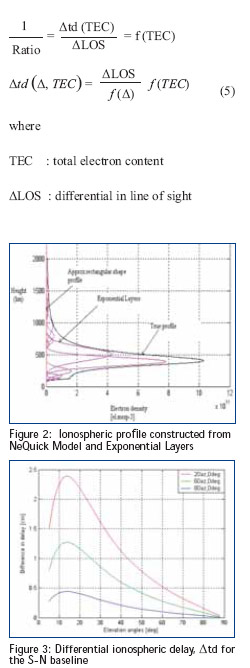
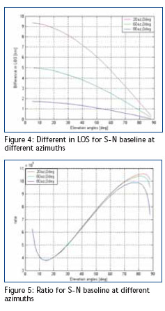
Global Positioning System (GPS) is currently one of the most popular global satellite positioning systems due to global availability of signal and performance. GPS employs two carrier frequencies which is L1 and L2 allowing receivers equipped with dual frequency operation to be used. Due to the inhomogeneity of the propagation medium in the ionosphere, the GPS signal does not travel along a perfectly straight line [1,2]. In addition, from Figure 1, the effects of the ionosphere can cause range-rate errors for GPS.


https://mycoordinates.org
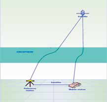
Figure 1: Exaggerated view of GPS signal in the ionosphere

The Earth’s ionosphere plays a crucial role in GPS accuracy because this layer represents the largest source of positioning error for the users of the GPS after the turn-off of Selective Availability (SA). In order to provide ionospheric corrections for positioning and navigation for singlefrequency GPS receivers, the ionosphere needs to be mathematically described by a given ionospheric model. A good model
for the equatorial region has become more important because of the need of higher accuracy GPS positioning. This means that further work on the equatorial area is essential when the ionosphere has become the most critical error source for GPS positioning. Accurate correction for the ionospheric error is necessary for increased accuracy, however the complexity of the model used should be consistent with the required accuracy. Meanwhile, precise ionospheric modelling is also important for other space-based observation systems as well as communication systems and space weather studies.
The ionosphere over Malaysia is unique because of its location near the equator line. The purpose of this work is to develop an accurate ionospheric model that best suits the equatorial region and that could get differential ionospheric delay in sub-centimetre accuracy.

Corrections and ionosphere models

Application of GPS for ionospheric sensing is now the subject of worldwide interest. In addition to this application, it has also been used widely in ionospheric study to model the electron content whilst the GPS signals propagate through the ionosphere. In this work, the ionosphereinduced errors in dGPS for short baseline are fi rst determined. After that the method of modelling and correcting these errors are provided. Very precise ray paths for both groups and phases were determined utilizing a modifi ed Jones 3-D ray tracing program, which includes the effect of the geomagnetic fi eld together with a Nelder– Mead algorithm to home in precisely on the satellite to earth station path [3].

Ionospheric error correction using modifi ed jones 3d ray-tracing
The 3D Jones ray-tracing program is numerical complex used to investigate the ionospheric effect for both carrier phase and group delay in transionospheric propagation. The minimization function was run to fi nd the satellite location at GPS altitude for every set of initial azimuth and elevation angles that were chosen for simulation. The ionospheric delay is a function of elevation angle so its variations are the main parameters to be consider in the modelling. The difference in ionospheric delay between paths to the reference and mobile stations for differential GPS has been quantifi ed for equatorial region.

Ionospheric profile using nequick model and exponential layer
The ionospheric model used in the ray tracing is determined by fitting a number of exponential layers to realistic ionospehric profile. In this work, the electron densityprofi le was fi tted with exponential layers and as input to improve the ray-tracing program. Figure 2 shows the process of fi tting the NeQuick ionospheric profile by 40 exponential layers and the vertical total electron content for this profile, which is for equatorial, is 31 TECU. NeQuick electron density profile has the electron concentration that can be calculated along an arbitrarily chosen-raypath and the resultant profi le is smooth (continuous fi rst-order spatial derivatives) which is important in ray tracing.

Ionospheric error correction on GPS signals due to the direction of mobile station base on reference station in DGPS
To obtain the LOS, the receiver and satellite positions should be known,
and there are several methods to obtain them. The difference in the delays (Δtd) between the paths can be found from the difference in delays between the reference and mobile stations.

Δtd=tdref-Δtdmob (1)
The difference in LOS (ΔLOS) can be found from the difference in LOS between the reference and mobile station as eqn. (2). The real time satellite position is suffi cient in this application and the precision of LOS is not so crucial compared to other parameters in the model.

LOS = LOSref -LOSm (2)
where LOSref : line of sight at reference station LOSm : line of sight at mobile station The relation between Δtd and the difference in true range (ΔLOS) for a given satellite position and their ratio as:

Ratio =https://mycoordinates.org(3)

The ionospheric error for two closely separated stations can be evaluated and corrected. Calculations were performed for both reference and mobile stations located at equatorial region to investigatethe ionospheric effect for both the carrier phase and group paths for L1and L2. Since the ionospheric delay is a function of elevation angle, its variations are the main parameters to be considered in the modelling so the variation of azimuth and baseline direction will be investigated. The TEC and profi le shape also will be investigated because it also infl uenced by ionospheric error.
Figure 3 showS that the difference in ionosphere-induced delay for South-North (S-N, 0˚) baseline direction for baseline length of 10 km.. Three azimuth angles (α=20˚, 60˚ and 80˚) were investigated for
these baseline directions for 30 elevation angles ranging from 5˚ to 89˚ with an ionospheric profi le of 72 TECU. Δtd is largest at lower azimuth (α=20˚) and lowest at higher azimuth (α=80˚). At 20˚ azimuth it has a maximum of 2.4 cm at 13˚ elevation, decreasing to 0.5 cm at 60˚ elevation angle. At 80˚ azimuth, it is less than 0.5 cm for any elevation angle. Figure 4 shows the different in LOS, ΔLOS between paths to the reference station and mobile station. Due to Figure 4, for the S-N baseline direction, ΔLOS is larger at lower azimuth as well as lower elevation. It is about 9.5 km at 20˚ azimuth and 5˚ elevation The ratio for the S-N direction is almost constant with azimuth at lower elevations but slightly dependent on azimuth at high elevations as shown in Figure 5. Δtd is actually higher at 20˚ azimuth at elevations less than 40˚ but so is ΔLOS.
Results also show that the ratio is independent of orientation of the baseline and azimuth angle. The above baselines located at equatorial region show a similar variation of the ratio with elevation and dependence on the TEC value.

Modelled the ratio using polynomial function
The ratio for S-N direction was modelled for the range of β up to 60˚ by fi tting the obtained relationships with polynomial functions, f (β) as defi ned in Eqn. (4). It should not be extrapolated outside this range to higher elevation angles(80 to 90˚). The baseline was 10 km length and it used 16 elevation angles.
f (β) = 8.1 × 10²β10 − 3.7 × 10³β9 +
4.5× 10³β8 +2.7× 10² β 7 − 4.7× 10²β 6 −
8.1× 10³β5 + 1.4 ×10⁴β4 − 3.2 × 10⁴β3+
5.2× 10⁴β2 + 2× 10⁵β +4.8 ×10⁵ (4)

Differential ionospheric delay model
Currently ionosphere modeling using GPS data is a useful effort. As a function of elevation angle and TEC, this model is applicable at equatorial region and only requires a single frequency receiver provided the TEC over reference station is known. The difference in ionospheric induced error between two stations can be expanded as:

β : elevation angle at reference station
Δtd : differential delay, in metre

https://mycoordinates.org

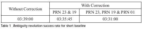
For accurate result, the carrier phase was primarily used instead of code pseudorange measurements. However, the integer ambiguity needs to be resolved. The infl uenced of the model can be examined by looking into its effect on the quality checking and on the carrier phase ambiguity resolution. Employing the ionospheric delay model and ambiguity resolution The integer ambiguity is the unknown integer number of whole cycles between satellite and receiver. The receiver can determine only the fractional part of the wavelength but not the integer, so the ambiguity resolution is essential for precise range determination [4].
The goal of ambiguity resolution is to resolve phase ambiguities, i.e. to obtain the correct integer numbers (ambiguity fi xing), which is possible at the DD level due to the elimination of instrumental biases etc. So a good ionospheric model is essential in order to get unambiguous results or reduce time to resolve for the ambiguities. After the ambiguities are resolved, the variance ratio is larger and the reference variances are smaller.

In order to illustrate the contributions of the correction ionospheric model, a shorter time (less than one hour period from 03:00:00 to 03:59:45) for KTPK station and UPMS station which is 19.75 km was chosen to see how the correction infl uenced the ambiguity resolution where the observed satellites PRNs are 01, 03, 19 and 23 from both stations were selected. Float solution non integer ambiguity estimate is produced when the processing cannot resolve the ambiguity. On the other hand, when the processing can resolve the ambiguity to a correct integer number, it results in a fi xed solution.

Table 1 illustrates that with these 4 satellites, (uncorrected data) the ambiguities were resolved with the occupation time of 03:39:00. By applying the correction model to PRN 23 and 19, ambiguities were resolved at 03:35:45, which is 00:03:55 earlier corresponding to uncorrected data and when the correction model was applied to PRN 23, PRN 19 & PRN 01, ambiguities were resolved at 03:31:00 which is 00:04:45 earlier corresponding to corrected data with PRN 23 and 19 only and 00:08:00 earlier compared to four satellites (uncorrected data).

https://mycoordinates.org

Conclusion

The work presented here has shown promising results based on the utilisation of carrier phase observation for precise positioning. The model is mostly suitable for short baseline. Simultaneously the model could also be preferably used among the single frequency users. The results show an improvement in the correction of the differential ionospheric error over short baselines. By applying the ionospheric model the ambiguity resolution success rate is faster even when only correcting one satellite seen at low elevation angles. After the ambiguities are resolved, the variance ratio is larger and the reference variances are smaller. From the model we can get differential ionospheric delay in sub-centimetre accuracy.

Acknowledgements

We are grateful to Jabatan Ukur dan Pemetaan Malaysia (JUPEM) for providing the GPS data. The authors also would like to acknowledge Dr. H. J. Strangeways and Dr. R. T. Ioannides of Leeds University for permission to use a part of the ray-tracing program.

References:

[1] E. Sardon, A. Rius and N. Zarraoa, Estimation of the transmitter and receiver differential biases and the ionospheric total electron content from Global Positioning System observations, Radio Science29, 1994, pp. 577-586,
[2] J. A. Klobuchar, B. W. Parkinson & J.J. Spilker, Ionospheric effects on GPS, in Global Positioning System: theory and applications, 1, ed.
American Institute of Aeronautics and Astronautics, Washington D.C., 1996.
[3] Ionnides R.T and Strangeways H.J., Rigorous calculation of ionospheric effects on GPS earthsatellite paths using a precise path
determination method. Acta Geod. Geoph., 37, 2002, pp 281-292.
[4] Donghyun K., and Richard B. Langley, “GPS Ambiguity Resolution and Validation: Methodologies, Trends and Issues”, International Symposium on GPS/GNSS, Seoul, 2000

Norsuzila Ya’acob

Department of Electrical, Electronic and Systems
Engineering,Universiti Kebangsaan Malaysia, Malaysia
norsuzilayaacob@yahoo.com

Mardina Abdullah

Department of Electrical, Electronic and Systems
Engineering,Universiti Kebangsaan Malaysia, Malaysia
mardina@eng.ukm.my

Mahamod Ismail

Affi liate fellow, Institute of Space Science, Universiti
Kebangsaan Malaysia, Malaysia
mahamod@eng.ukm.my
–~~~~~~~~~~~~–
The article presents views and opinion about current issues and priorities surrounding Geomatics and GNSS by experts in their repective domain.

Prof P Misra

Consultant in Land
Information Technologies
misralit@hotmail.com
Geographical Information System (GIS) has taught us that all surveying and mapping projects in the future have to be dependent on multi-disciplinary surveys with accurate ground control points provided by the national surveying organisations. This leads us to think that an appropriate structure/interconnection of the various organisations presently entrusted with the surveys should be brought together. Example, topographical surveys, geological surveys, forest surveys, soil and land use surveys etc. The present attempt is to propose a concept of structure which will provide the necessary linkages along with some future objectives.

National Spatial Data Infrastructure

The Ministry looking after the NSDI should be the overall in-charge of
ALL surveys, as mentioned above. The chief coordinator will, in real sense, be the Surveyor General of India. The present Surveyor General of India, the Head of Survey of India should have a new designation.
The revamped NSDI will lay the performance objectives of the constituent organisations under it.

NSDI: Additional Duties/Charter

• Applications of Satellite Imagery and Remote Sensing technology to be made more intensive and should form the basic inputs on laid out production norms of surveying and mapping. Department of Space should enhance its program on applications as compared to the Technology.
• Cadastral Surveys: There is a wide gap in technological practices in cadastral/revenue departments of the various states. NSDI should have a special Division exclusively for assistance to the states for upgradation of their standards. It should also run and recognize Training, R&D, Publications and Fellowships for the benefi t of the state personnel. Formulation of Policies regarding Geomatics NSDI should be the nodal organisation to advise other Ministries – e.g. Defense on the impact of the policies like restriction etc.

Education and Training

Survey Training Institute, Hyderabad and Indian Institute of Remote Sensing, Dehradun are two premier education and training organisations. These should be merged and redesigned towards becoming a Surveying University. This university should also be engaged in R&D, and Publications. NSDI should provide the necessary ‘extension’ services to this University.

Chairs in Geomatics

Professorial ‘Chairs’ should be established at IIT (Roorkee), Anna University, Chennai, IIRS Dehradun and Survey Training establishment at Hyderabad under the budget of the Central Government.

Balance between Government and Private Sector in Geomatics

NSDI should oversee that the private sector is well represented in Geomatics Sector in India. In Summary, stress in the future should be on the applications of technology, effi cient Geomatics products and services with international outlook and marketing practices. My earlier paper should be seen for further ideas on this subject.

My coordinates
EDITORIAL
Conference
GSDI 11 WORLD CONFERENCE
News
INDUSTRYLBS | GPSGIS | REMOTE SENSING | GALILEO UPDATE
Mark your calendar
JUNE 09 TO DECEMBER 2009

«Previous 1 2View All| Next»

Pages: 1 2

1 Star2 Stars3 Stars4 Stars5 Stars (No Ratings Yet)
Loading...