| Geodesy | |
Malaysia precise geoid (MyGEOID)
|
||||
|
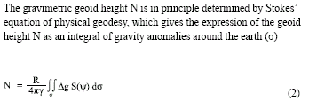
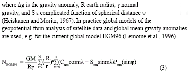
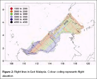
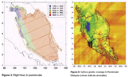
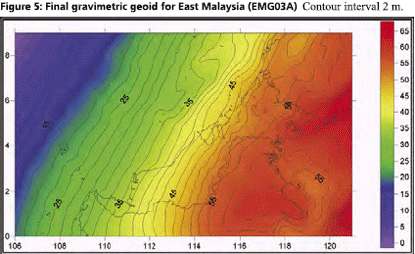
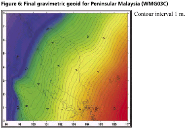
GPS infrastructures that have been established in Malaysia are mainly served as a ground control stations for cadastral and mapping purposes. Another element that has not been utilised is the height component due to its low accuracy. Conventional levelling is still the preferred method by the land surveyors to determine the stations orthometric height (H) with a proven accuracy. Therefore, Department of Survey and Mapping Malaysia (DSMM) has embarked the Airborne Gravity Survey, with one of the objectives is to compute the local precise geoid for Malaysia within centimeter level of accuracy. With the availability of the precise geoid, the “missing” element of GPS system is solved. The Malaysian geoid project (MyGEOID) is unique where the whole country is covered by with dense airborne gravity, with the aim to make the best possible national geoid model. The basic underlying survey and computation work of the Malaysian geoid project was done by Geodynamics Dept. of the Danish National Survey and Cadastre (KMS; since Jan 1 part of the Danish National Space Center) in cooperation with JUPEM. With the new data the geoid models are expected to be much improved over earlier models (Kadir et al. 1998). ObjectivesThe main objective of the Malaysian geoid model (MyGEOID) is to be able to compute orthometric heights H that refer to the national geodetic vertical datum (NGVD). Mathematically, there is a simple relation between the two reference systems (neglecting the defl ection of the vertical and the curvature of the plumb line): where, hGPS is the GPS height above the ellipsoid and N the geoid seperation. In the above equation it is important to realize that H refers to a local vertical datum, hGPS refers to a geocentric system (ITRF/ WGS84), to which the computed (gravimetric) geoid also usually refers. the possibility of using GPS leveling technique, knowing the geoidal height N, the orthometric height H can be calculated from ellipsoidal height h. Deriving orthometric height using this technique with certain level of accuracy, could replace conventional spirit leveling and therefore make the levelling procedures cheaper and faster. The existence of datum bias (differences between geoid and local mean sea level) will not gives satisfactory results if based on the above formula. In order to overcome this problem, fi tting the gravimetric geoid onto the local mean sea level (NGVD) will minimize the effect of datum biases. Gravity data acquisition and processingGravity dataThe Malaysian airborne gravity survey was done on a 5 km line spacing, covering mostly Sabah and Sarawak in 2002 and Peninsular Malaysia in 2003. The airborne gravity data system used was based on the Danish National Space Center (DNSC)/University of Bergen system, used extensively for Arctic gravity field mapping. The system is based on differential GPS for positioning, velocity and vertical accelerations, with gravity sensed by a modifi ed marine Lacoste and Romberg gravimeter. The system has a general accuracy better than 2 mgal at 5 km resolution. For the Malaysia airborne survey, the system was installed in a An- 38 aircraft (Figure 1, below), and the aircraft turned out to be very suitable for the airborne survey, with accuracies estimated from crossovers well below 2 mgal r.m.s. The airborne gravity survey was flown at different elevations, as topographic conditions permitted, see Figure 2 and 3. The data were therefore required to be downward continued to the surface, before applying the Stokes formula gravity to geoid transformation. The downward continuation was done by least-squares collocation using the planar logarithmic covariance model (Forsberg, 1987), using all available gravity data in the process (airborne, surface, marine and satellite altimetry gravity data). The Stokes’ integration was implemented by spherical FFT methods (Forsberg and Sideris, 1993). The existing surface gravity data coverage was only of signifi cance in Peninsular Malaysia (Figure 4). Here the relatively dense surface gravity data coverage in the lowlands will strengthen the geoid compared to the situation in Sabah and Sarawak, where a minimum gravity data was available. Gravimetric GEOID computationFor the Malaysian project new GRACE satellite data combination models were used (GGM01C). This model is a combination model to degree 180 based on 1° mean anomalies, essentially derived from the same terrestrial data as EGM96, but having superior new satellite information (GGM01S) at the lower harmonic degrees. A third data source for the geoid determination is digital terrain models (DEM’s), which provide details of the gravity field variations in mountainous areas (the mass of the mountains can change the geoid by several 10’s of cm locally). The handling of digital terrain models is done by analytical prism integration assuming known rock density (Forsberg, 1984). The new satellite data SRTM was used together with JUPEM DEM’s for this purpose. With the data from spherical harmonic models, local or airborne gravity, and DEM’s, the (gravimetric) geoid is constructed by removerestore techniques as a sum The summary of gravity data used in the gravimetric geoid computation are tabulated in Table 1 and the computed geoid models for Sabah and Sarawak (EMG03C) as in Figure 5 and Peninsular Geoid model (WMG03A) as in Figure 6. |
||||
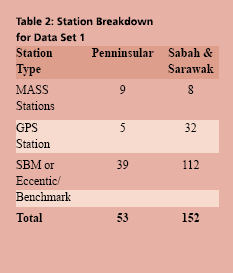
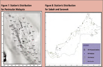
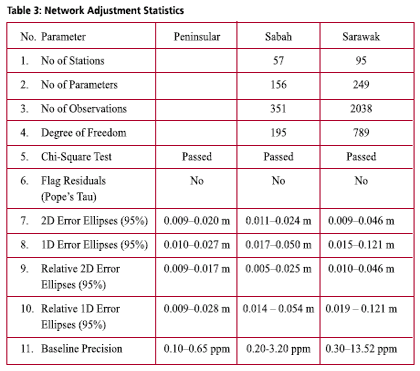
Fitted GEOID modellingThe existence of datum bias (differences between geoid and local mean sea level) will not gives satisfactory results if based on direct reduction formula (1). In order to overcome this problem, fitting the gravimetric geoid onto the local mean sea level (NGVD) will minimize the effect of datum biases. GEOID modelling by surface fittingThe most common method in geoid modeling techniques is by fitting a surface on a reference points. In this fitted geoid modelling, the strategy is to fi t the gravimetric geoid for Peninsular Malaysia (WMG03A) to the geometric model or sometimes referred to as a “GPS-geoid” (Forsberg 1998). NGPS = hGPS – Hlevelling (5) However, in a local area, determined geoid model with surface fi tting just works in the coverage area of the reference points properly. The model doesn’t give reliable results for the extrapolation points. Researches shows that this method gives better results where the geoid have a regular trend and with well distributed and intensive reference points, and it is essential that both levelling and GPS height are as error-free as possible. The fitting of the gravimetric geoid to GPS-geoid surface is in the grid form and involve modeling the differences:) By adding the correction Where, NGPS(i) and NGrav(i) are the geoidal height at point (i) obtained from gravimetric and GPS-geoid models respectively. a1 to a4 are the four unknown parameters, The geoid undulations of interpolation points were determined according to Least Squares Collocation (LSC) method. Collocation is the most general form of the adjustment process which includes least squares adjustment, filtering and prediction (interpolation, extrapolation) steps with in a combined algorithm. In the process the covariance function must be determined for the residuals geoid errors In the Gravsoft software package the covariance model of a second order Markov model is used (Forsberg 1998). GPS data acquisition, processing and adjustmentData acquisitionGPS observation on Benchmark project was carried out by DSMM in 2003 and 2004. GPS Observation period for the data sets are between 4 – 9 hours, with the observations divided into three separate network for Peninsular, Sabah and Sarawak. A total of 53 stations have been observed in Peninsular and 133 stations in Sabah and Sarawak. The station breakdowns are tabulated in Table 2, and stations distribution for Peninsular and Sabah and Sarawak as in Figure 7 and 8 respectively. GPS data procesing and adjustmentBernese GPS Post Processing Software Version 4.2 has been used to process the whole GPS campaign data for Peninsular and Sabah, and Trimble’s Geomatic Offi ce (TGO) Version 1.61 was used for GPS data from Sarawak. The standard processing strategy as employed by DSMM were used with the following parameters for Bernese 4.2: The output from the data processing is the stations coordinates with it respective covariances and the resolved baseline ambiguity is at the level between 60 – 90 %. The GPS network adjustment was carry out using Geolab adjustment software from Microsearch Corparation for the three independent GPS networks of Peninsular, Sabah and Sarawak. The adjustment of the networks is based on the new Geocentric Datum for Malaysia 2000 (GDM2000) and the standard error modeling and scaling have been adopted. The statistics of the adjustment results are as in Table 3. Levelling networkThe vertical control in Peninsular Malaysia, Sabah and Sarawak was constructed separately. The new height datum for Peninsular Malaysia was determined in 1994 based on the mean sea level (MSL) value from the tide gauge in Port Klang after more than 10 years of observation (1984-1993). The height was transferred from Port Klang using precise levelling to a Height Monument in Kuala Lumpur by 3 different precise levelling routes. In Sarawak, there are six vertical datums known as Pulau Lakei Datum, Original Datum, Bintulu Datum, Merapok Datum, Limbang Datum and Sabah Datum. Pulau Lakei Datum and Original Datum are based on MSL 1955 and MSL 1935 respectively. Meanwhile, Bintulu Datum and Merapok Datum are based on triangulation station network heights which are connected to Pulau Lakei Datum and Original Datum. Limbang Datum is referred to a year of tidal observation at Limbang Jetty and Sabah Datum refers to one month tidal observation at Sipitang in 1949. As for Sabah, beginning 1997, all levelling network that has been run by DSMM refers to MSL in Kota Kinabalu based on 10 years of tidal observation (1987-1997). The leveling network in Sabah and Sarawak has recently unified by adopting the MSL value from Kota Kinabalu Tide Stations. |
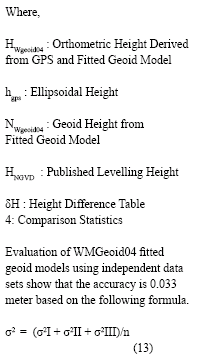
Fitted GEOID modellingPeninsular malaysia (WM Geoid04)A total of 39 Benchmark observed with GPS have been used in the computation of Peninsular Malaysia fitted geoid model. The computation was done iteratively, and the results in every iteration, closely examined in every iteration. Figure 11, shows the corrector surface range between 0.95 – 1.60 m, with two stations namely S0220 (minimum Diff.) and E1142 (maximum Diff.) shows the bull-eyes characteristic. Investigation on the suspected stations show that E1142 located on the highland (Cameron Highland) and S0220 is at the tip of Peninsular Malaysia (Sungai Rengit). Both SBM connected using precise leveling survey but not in the form of leveling loop (hanging line). The levelling lines are also not in the main adjustment of the Peninsular Malaysia Precise Levelling Network. In the second iteration, S0220 and E1142 were excluded from the process, and the results show an improvement with the corrector surface is well distributed (Figure 12). The corrector surface range is between 1.14 – 1.44 meter with the formal standard error is 0.020 m in the least square collocation adjustment. Sabah and Sarawak (EMGeoid05)In Sabah and Sarawak, 60 out of 71 benchmarks with MSL values were used in the fi tted geoid model computation. Sixiterations have been carried out with eleven benchmarks excluded before the final fitted geoid model finalized. Figure 13 shows the corrector surface that range between 0.55 – 1.75 meter from the fi rst iteration. The plot clearly shows the “bull-eyes” that represent the existent of outliers in one of the input component. In the subsequent LSC adjustment, benchmarks which suspected as outliers removed. The final 6th iteration with 60s benchmarks yield the formal error of 0.029meter with corrector surface range between 1.10 – 1.45 meter. Quality assessmentIn order to have more realistic assessment of the WMgeoid04 model, comparison using three independent data sets has been carried out. Basic Formula: This value is more realistic when compare to the formal error of 0.020 m from the LSC adjustment. From a total of 115 benchmarks that have been evaluated (Data 1, II and III), only 13 benchmarks (11.3%) were found to be an outliers. For EMGeoid05, only one set of independent data are available with achievable accuracy of 0.042 meter. ConclusionsThe Malaysian gravimetric geoid is apparent accurate to few cm r.m.s, with larger errors closer to the international borders (Forsberg, 2005). The geoid is fi tted to GPSlevelling information, and any errors in HLevelling and hGps, will directly affect the high quality of the gravimetric geoid; in other cases it will help control longer wavelength errors. The balance between fit of GPS, and errors in geoid and GPS, is delicate, and undoubtedly there will be many regions in the present geoid where GPS users can expect problems due to fi tting of GPS-levelling data with errors. Based on the statistical analyses, it can be concluded that the accuracy of fitted geoid models of WMGeoid04 and EMGeoid05 is 0.033 and 0.042 meter respectively, and can be used for height determination. To achieved certain level of accuracy in determination of orthometric height (H), accuracy of observed GPS network has to be better than 1 ppm (relatively) and the vertical errors (95% Conf. Region) have to be less than 3 cm Real Time Kinematic (RTK) survey and MyRTKnet service provided by DSMM with 3 cm level of accuracy can make use of the models for engineering survey, rapid height monitoring and establishing levelling route. RecommendationFitted geoid model WMGeoid04 and EMGeoid05 is the product of GPS on Benchmark observation. In order to improve the results and to achieve 1 ii. The existing Precise Levelling Network based on spirit levelling carried out from 1985 to 1995. The levelling networks need to be carefully analyzed, and possibility of carry out a new adjustment including analysis of subsidence and land uplift. iii. Resurvey by levelling and GPS of selected, suspected erroneous points with large geoid outliers. iv. If long GPS observation is needed, GPS processing software must be capable of producing the solution with the statistic and to model the troposphere with the adequate parameters. v. Make a new GPS-fitted version of the gravimetric geoid as new batches of GPS-levelling data become available, and as GPS users report problem regions for heights. vi. GPS levelling technique need the antenna height measure correctly. The use of stable Bipod with fixed antenna height will minimize the error especially with the shorter baselines. vii. Levelling route is always following the federal and states road, hence, Bibliography:B. Hofmann-Wellenhof, H. Lichtenegger, and J. Collins (1997): GPS Theory and Practice 4th , Revised Edition, SpringerWienNewYork. Erol B & Nurhan Rahmi (2004): Precise Local Geoid Determination to Make GPS Technique More Effective in Practical Application of Geodesy, FIG Working Week 2004, Athens, Greece. Forsberg R, Oleson A, Bastos L, Gidskehaug A, Meyer U, and Timmen L (1999): Airborne Geoid Determination, Earth, Planets and Space , Tsukuba, Japan. Forsberg R (2000/2002): Basic of Geoid Determination – With Applications to the Nordic area Geoid, Lecture Note for DSMM Malaysia. Forsberg R (2005): Towards cmgeoid for Malaysia, Seminar on MyGEOID and MyRTKnet, Kuala Lumpur, Malaysia. Fotopoulos G, Kotsakis C, and Sideris M.G (1999): Evaluation of Geoid Models and Their Use in Combined GPS/Levelling/Geoid Height Network Adjustments, Department of Geomatics Engineering, The University of Calgary, Alberta, Canada. Heiskanen W, and Moritz H. (1966): Physical Geodesy, W.H Freeman and Marti U, Schlatter A, Brockmann E, (2002): Combining Levelling with GPS Measurements and Geoid Information, Federal Offi ce of Topography, Wabern, Switzerland. Martensson S, (2002): Height Determination by GPS – Accuracy with Respect to Different Geoid Models in Sweden, FIG XXII International Congress, Washington D.C, USA. Pikridas C. et. al. (1999): Local Geoid Determination Combining GPS, Gravity and Height Data. A Case Study in the Area of Thessaloniki, Tech. Chron. Sci. J. TCG, I, No 3. Sverre Wisloff (2002):Deriving Orthometric Heights from GPS Measurement Using a Height Reference Surface, FIG XXII International Congress, Washington D. C, USA. Tscherning C . C (2002): Datumshift, error-estimation and grosserror detection when using leastsquares collocation for geoid determination, International School on the Determination and use of the geoid. Department of Geophysics, Universisy of Copenhagen, Denmark. Urs Hugentobler et. al (1999): Bernese GPS Processing Software Version P, and Krakiwsky E. J (1992): Geodesy The Consept Second Edition, Elsevier Science Publishers B. V, The Netherland. |
||||||||||||||||
|
||||||||||||||||
|







 (No Ratings Yet)


