| GNSS | |
GNSS authenticity verification in covered spoofing attack using antenna array
A covered spoofing scenario is considered in this research where the reception of the authentic signals are blocked and the receiver antenna only receives counterfeit signals |
 |
|
 |
|
Due to rapidly increasing applications of GNSS dependent systems, motivation has increased to spoof these signals for illegal or concealed transportation and to mislead receiver timing used by critical infrastructure. Detection and mitigation of spoofing attacks on GNSS receivers has become an important research topic [1-5]. Spoofing countermeasure methods analyse specific features of the counterfeit signals which may enable a receiver to distinguish them from authentic signals.
The spoofing detection techniques implemented at the pre-despreading and post-despreading signal processing layers of a GNSS receiver are effective and can detect spoofing attacks in presence of authentic signals [6-11]. Pre-despreading metrics have been employed to detect the presence of excessive amount of power in GNSS bands [12-13] and [16]. The received signal strength (RSS) spoofing detection approaches generally rely on the assumption that spoofing signals are more powerful than the authentic ones and a successful spoofing attack transmits several counterfeit GNSS-like signals. These methods evaluate the overall power of the received signal set without separately analyzing different signals. This category of spoofing detection analyse any abnormal variation in the received signal power prior to the despreading process in the receiver. The power-based spoofing detection methods requires calibration to be performed under the non-spoofed condition. Post-despreading methods are employed to detect an abnormal behaviour of cross-correlation function which may be caused by the presence of both genuine and counterfeit signals [14- 15]. The interaction between authentic and counterfeit signals causes distortion on the shape of the correlation function. Signal Quality Monitoring (SQM) tests focus on this feature in order to detect any asymmetry and/or abnormally sharp or elevated correlation peaks due to the presence of undesired signals [15].
It is important to note that these methods make the ctitical assumption that both authentic and spoofing signals are present and the receiver is initially tracking authentic signals. Hence, in absence of authentic signals, when only counterfeit signals are received, these two assumptions are invalidated, and so these methods may no longer work. This may occur, for example, when the GNSS antenna is covered and only exposed to counterfeit signals, or overpower non-overlapped spoofing attack and the receiver is exposed to counterfeit signals during cold start.
An antenna array processing is another approach to detect and mitigate spoofing attacks [14],[17-20]. Under the assumption that all counterfeit signals are broadcast from a single spoofing source, this approach takes advantage of the similarity between the angle-of-arrival (AoA) of counterfeit signals. Algorithms applied to the signals received using an antenna array can classify signals according to their respective AoA and to steer a null in the directions from which the counterfeit signals arrive. At the pre-despreading level antenna arrays can be also used to extract the spatial signature of counterfeit signals without acquiring and tracking the counterfeit and authentic signals [21- 22]. The receiver structure in the antenna array case consists of several antennas each connected to a separate radio frequency down-conversion channels and digitizers in a phase coherent mode usually utilizing a single reference oscillator and synchronized voltage controlled oscillators. The antenna elements separation in such cases is about half of the carrier wavelength and the antenna array is generally considered a single receiver unit for a specific application [23-24].
The counterfeit signals sourced from a single antenna have the same spatial signature, which means that all the signals experience the same channel parameter variation in the spatial domain. This can be used as a metric to detect a spoofing attack. The spoofing detection unit places all signals with the same spatial signature in the spoofing group. The advantage of the antenna array processing over the single antenna spoofing detection methods is that it can detect spoofing attack in absence of authentic signals (in the covered antenna case) as long as spoofing signals are transmitted from a single antenna.
Herein a covered spoofing scenario is defined to establish a foundation to analyze sensitivity of different spoofing detection methods. The receiver equipped with an antenna array is covered to block reception of authentic signals where a small antenna connected to a spoofing generator transmits an ensemble of counterfeit signals which are received by the antenna array. Then detection performance of the antenna array processing based on the near-filed signal propagation is analyzed. The performance of single antenna spoofing detection metrics including IF sample variance and SQM methods will be also investigated.
Spoofing detection metrics
Several spoofing detection metrics in different operation layers of a GNSS receiver have been proposed. These metrics can generally be divided into two categories, namely pre-despreading and post-despreading techniques [3]. In the following some of them are introduced.
Pre-despreading spoofing detection
Different spoofing detection methods based on monitoring the received signal strength are discussed here. These techniques rely on the assumption that counterfeit signals are more powerful than the authentic ones. Pre-despreading methods analyse the overall power content of the received signal set without separately analyzing different signals. This type of counterfeit signal detection examines any abnormal variation in the baseband signal power prior to further processing signals. At this stage, the GNSS signals are buried under the noise floor and a spoofing detection test is performed based on the analysis of the power content of the received baseband signals.
Baseband variance analysis
This method continuously monitors the variance of baseband signals in order to detect additional power injected by interference signals. Most commercial GNSS receivers are equipped with an automatic-gain-control (AGC) module that adaptively changes the receiver input gain based on the variance of the received signal in order to efficiently use the quantization levels of the input analog-todigital- convertor (ADC) module, and to protect the baseband amplification stages from excessive power. A feedback circuit controls the AGC gain and monitoring of this gain value is used to detect variations in signal variance due to the presence of interference. In the case of fixed AGC gain and adequate ADC digitizer bits, the IF sample variance can be used to monitor the excessive power in the band. This method does not take advantage of any signal structure and simply assumes that the counterfeit signals’ power content elevates the ambient noise floor. A spoofing (or generally interference) attack will be detected if the estimated variance is higher than a predefined detection threshold. Defining a proper detection threshold requires an initial power level calibration in the presence of clean signals in a typical operational environment.
Structural Power Content Analysis (SPCA)
SPCA takes advantage of the cyclostationarity of GNSS signals in order to detect excessive amount of structured signal power in the received sample set [3]. In this approach, the received IF samples are first filtered within the GNSS signal bandwidth and then multiplied by their one-chip delayed version in order to remove the effect of Doppler frequency. The resulting signal has a line spectrum since it is generated by multiplication of cyclo-stationary signals. In the next stage, the signal and noise components are filtered by suitably designed comb filters [3]. A detection test statistic is calculated based on the filter outputs and is then compared to a threshold in order to differentiate between the presence and absence of counterfeit signals. Since each PRN signal is received from a different satellite with different relative dynamics with respect to a user, their corresponding Doppler frequencies are different from each other. Therefore, in order to concentrate all signal components on the same spectral lines and facilitate spectral filtering, the Doppler shifts of the signals should be removed. To this end, the sampled baseband signal components are first multiplied by the complex conjugate of their one chip delayed version. This operation removes the phase rotation due to the Doppler frequency of received signals. It also removes the navigation data bits and secondary codes and GNSS subcarriers that are modulated on each spreading code.
Post-despreading spoofing detection
Herein some of the widely applied spoofing detection methods are described.
Effective C/N0 analysis
Effective C/N0 analysis is a common signal strength monitoring metric that is available in most commercial receivers. The effectiveness of this metric towards the classification of an interference signal is investigated herein. Generally, three terms can affect the effective C/N0. The first one corresponds to the noise component due to thermal noise or other interference sources, the second refers to the cross correlation between counterfeit signals and authentic replica and the third refers to the cross correlation caused by other authentic signals. The cross correlation term caused by high power spoofing signals can become the dominant term which is directly proportional to the power level of spoofing signals. This term considerably reduces the effective C/N0 of authentic PRNs and leads to saturation of spoofing C/N0 values.
The upper limit of a GNSS signal power level is known a priori. Hence, for a given receiver, an upper limit for the C/ N0 value can be defined. The spoofing detection metric based on C/N0 monitoring works based on this fact. An abnormally high C/N0 value can be an indication of a spoofing attack. In addition, jamming signals also affect the effective C/N0 values by increasing the noise floor. A constructive multipath signal can cause a C/N0 value to exceed the spoofing detection threshold and result in a false alarm. Hence, this metric should be used in conjunction with other spoofing detection metrics to reduce false alarm probability.
SQM
The interaction between authentic and spoofing signals causes distortion on the shape of the correlation function. Signal Quality Monitoring (SQM) tests focus on this feature in order to detect any asymmetry and/or abnormally sharp or elevated correlation peaks due to the presence of undesired signals [25]. This metric is originally designed to monitor the correlation peak quality affected by multipath signals and has been widely used in the monitoring of signal quality in applications that require high integrity, such as aviation and rail.
One of the advantages of SQM tests is that they are not highly dependent on training or a calibration process based on a clean data. As mentioned previously, SQM metrics are designed to monitor correlation peak distortions due to multipath or overlapped spoofing attack. As such, they may exhibit high false-alarm rates under multipath conditions. Moreover, in the case of covered or non-overlapped spoofing attacks these metrics are not effective.
GNSS signals authentication using antenna array processing
A receiver equipped with an antenna array can employ spatial filtering techniques in order to shape its reception beam pattern. This type of receivers can steer a null toward the spoofing source and suppress its destructive effect [23]. Antenna array processing to detect spoofing attacks can be implemented at the pre-despreading (IF sample level) or post-despreading stage of a GNSS receiver. In the following each implementation approach are discussed.
Pre-despreading spoofing mitigation
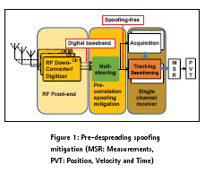
Assume a spoofing attack scenario where a single source spoofer propagates several counterfeit PRNs. A low computational complexity multi-antenna spoofing detection and mitigation method that is able to spatially filter out the spoofing signals has been proposed in [22]. This method cross-correlates the baseband samples from different antennas in order to form a spatial correlation matrix and extract the spatial signature of the spoofing source. The steering vector corresponding to the spoofing signals can be extracted since all of the spoofing signal energy is coming from the same spatial sector. This type of spoofing detection approach considers the spoofing source as a wideband interference signal and successfully detects and mitigates the spoofing source. Considering the fact that several spoofing PRNs impinge on the antenna array from the same direction, it can be observed that their power outputs are added constructively from a specific spatial sector. In other words, the spatial power density of the spoofing signals is considerably higher than that of the authentic signals. The spatial correlation matrix of the received signal can be constructed to estimate spoofing steering vector. To estimate the spoofing sub-space or equivalently the spoofing steering vector one can employ Eigen value decomposition of the spatial covariance matrix where the spoofing steering vector is related to the Eigen vector corresponding to the largest eigenvalue. One of the advantages of this method is that it does not require array calibration and its computational complexity is low. Figure 1 shows the block diagram of the pre-despreading spoofing detection and mitigation approach. Digitized baseband samples from a multiple-channel synchronized front-end are passed to the null-steering unit where the weights to suppress a spoofing signals are calculated. The output of the null-steering unit is baseband spoofing free complex samples that are passed to a conventional receiver acquisition and tracking module.
Post-despreading spoofing mitigation
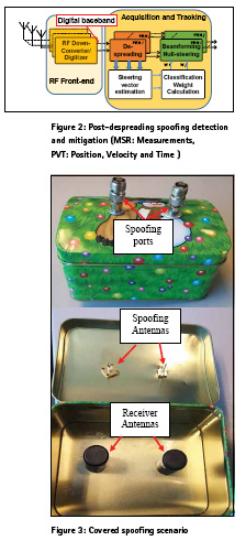
In post-despreading antenna-array based spoofing detection and mitigation methods the despreading and accumulation process are applied to each digitized baseband antenna samples. Figure 2 shows the post-despreading spoofing detection and mitigation block diagram. The output baseband samples from different frontend channels are first fed to the acquisition engine to detect available signals. The acquisition routine in this case is modified to detect all of the peaks above the detection threshold and passes all of the initial code phases and Doppler frequencies to the tracking unit. The despread samples of different detected signals are then fed to the steering vector estimation unit. The spoofing detection unit correlates the estimated steering vectors of all detected signals. High correlation among estimated steering vectors indicates that the signals are transmitted from a single source. The estimated steering vector then is passed to the classification and weight calculation unit. The output of the weight calculation unit is then forwarded to the beamforming and null-steering module. The output of the beamforming/ null-steering module is a single channel spoof free signal used to calculate GNSS measurements for different PRNs.
Here, it is assumed that the antenna array is not calibrated. More specifically the relative phase and gain of the antenna elements are unknown and the orientation of the array is not known. After tracking all spoofing and authentic signals, the spoofing detection module correlates the array responses (steering vector) of different signals. The spoofing signals sourced from a single antenna have the same spatial signature, which means that all the PRNs experience the same channel parameter variation in the spatial domain. This can be used as a metric to detect a spoofing attack and classify spoofing and authentic signals. Covered Spoofing Attack
This section describes the data collection procedure used to analyse different spoofing detection metrics under covered spoofing attack.
Data collection and processing
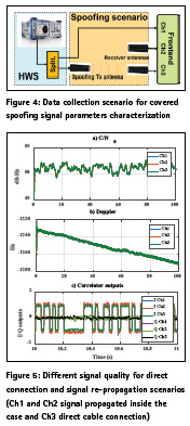
In the covered spoofing attack investigated in this paper the receiver antennas were enclosed to avoid reception of authentic signals while the spoofer propagates counterfeit signals. An antenna array with two Maxtena helical antenna elements with 8 cm spacing was used for spatial processing. Data was collected with a phase-coherent multi-channel Fraunhofer/TeleOrbit RF front-end with 10 M samples/s, 8 bit quantization and disabled automatic gain control (AGC). A metallic case was developed to cover the receiver antenna array. The antenna array was placed inside the case where authentic signals reception were blocked and the array was exposed to only counterfeit signals. The covered spoofing scenario is shown in Figure 3. There are two input ports for spoofing propagation and two receiver antennas for antenna array processing. Data was collected in two cases namely open sky and under covered spoofing attack. In the open sky scenario, the two-element antenna array was exposed to a clear open sky during the data collection. In the spoofing scenario, the receiver antenna array was placed inside the metallic case shown in Figure 3. Spoofing data was collected inside a lab where the spoofing antenna propagated counterfeit signals inside the case and captured by the receiver’s antenna array. A hardware simulator was used to generate counterfeit signals. The counterfeit signals power level were tuned beforehand in a calibration process to be received at the receiver antennas with the same power level as that of the authentic signals.
Signal quality in the covered spoofing scenario
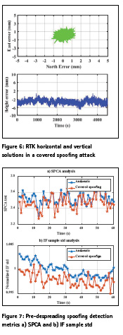
The first step to develop proper counterfeit signal detection metrics in the covered spoofing attack is to characterize the signal parameters. Since the counterfeit signals are propagated inside the case the received signals by the receiver antennas may be subject to attenuation and multipath propagation which may affect the received signal quality and hence receiver performance. This investigation may lead to some counterfeit signal detection metrics. To this end a data set was collected to analyse the performance of signals propagation inside the case. The data collection procedure is shown in Figure 4. The hardware simulator signal output was connected to a two way splitter where one of the outputs was connected directly to one of the front-end channels. The other splitter’s output was connected to the spoofing port to propagate signals inside the case which then received by the receiver antennas. These signals were sampled with the RF front-end as shown in Figure 4 in a phase coherent fashion. The IF samples captured by these three channels were processed by a software receiver. Figure 5 shows different signal quality measures namely C/N0, Doppler values and I/Q outputs for the three channels for a given PRN. As shown the C/ N0 values from different channels matches very well. This observation indicates that there is minimal signal power loss due to signal propagation inside the case compared to the direct cable connection.
Also as shown the multipath effect on the received signal strength propagated inside the case is negligible. The counterfeit transmit antenna was closer to the receiver Ch1 antenna as shown in Figure 4. This fact did not affect the C/N0 values neither due to the path loss nor due to multipath phase rotation. Figure 5b shows carrier Doppler values for the three channels. As shown all of the channels yield the same performance. Figure 5c shows the I and Q values of the correlator outputs. All the channels were operating with a PLL, hence all of the signal energy is concentrated in I branches. As shown the I and Q branches of different channels have the same signal level which verifies the proper signal level calibration. The observations shown in Figure 5 was for a given PRN and similar results were observed for other PRNs. The signal quality characterization for the covered spoofing scenario provided in Figure 5 was focused on individual PRN parameters. To further analyse the quality of code and carrier phase measurements in the covered spoofing attack the measurement outputs of the software receiver were converted to the RINEX format. The measurements from Ch1 (spoofing) and Ch3 (authentic) were passed to the RTKLIB software for carrier phase positioning. This is a zero-baseline test where Ch1 and Ch3 measurements were used as rover and base measurements, respectively. The carrier phase positioning results are shown in Figure 6. Figure 6a and Figure 6b shows the horizontal and vertical position errors respectively. As shown a fixed RTK solution with mm level positioning error can be achieved in this scenario.
Single antenna based spoofing detection metrics performance under the covered spoofing attack
In this section the outputs of some spoofing detection metrics implemented in the pre and post-despreading stages of a receiver in a covered spoofing attack are examined. To this end different metric outputs for direct cable connection as the authentic signals are compared to those of the spoofing signals propagated inside the spoofing case. Figure 7 shows SPCA and IF samples standard deviation (std) outputs. Each metric output is based on 1 s process of IF samples.
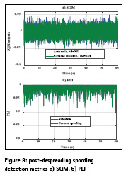
The SPCA outputs measures the amount of GNSS signal power in the band and since this amount is measurable in a clean data set the output of SPCA can be used to detect the extra signal energy in the GNSS bandwidth when both authentic and spoofing signals are present. However, in the covered spoofing case where the authentic signals are not present the output of the SPCA metric should be the same as the clean data set. As shown in Figure 7a the SPCA metric outputs have the same values in the case of authentic and covered spoofing attack. Figure 7b shows the normalized IF samples standard deviations for 60 s of IF samples. As shown the authentic and covered spoofing cases are not distinguishable based on this metric as well. Figure 8 shows post-despreading spoofing detection metrics namely signal quality monitoring (SQM) and phase lock indicator (PLI) for the authentic and covered spoofing cases for a given PRN.
A delta metric SQM outputs with monitoring correlator spacing of 0.4 chip was employed in this case. As shown the SQM outputs in both cases are identical with similar statistics shown in Figure 8a. PLI values are shown in Figure 8b for the authentic and covered spoofing cases. As shown PLI values are comparable in both of the authentic and spoofing cases.
Multi antenna based spoofing detection metrics performance under the covered spoofing attack
As shown in the previous section the single antenna based spoofing detection metrics were not sensitive to the covered spoofing attack. This make sense since these types of counterfeit signal detection metrics rely on the power analyses or distortion on the correlation functions and none of these occur in the overlapped spoofing scenario.
In this section the performance of antenna array processing for counterfeit signal detection is analysed.
It is assumed that the antenna array is not calibrated. More specifically the relative phase and gain of the antenna elements and the orientation of the array are unknown. To this end the IF samples output of the RF front-end was processed in two steps namely pre-despreading and post-despreading. In the pre-despreading stage the 2×2 spatial correlation matrix averaging over 1 s of data constructed. In the authentic signal scenario since all signals are transmitted from different directions the signal energy does not add up constructively and hence the eigenvalues of the spatial correlation matrix should have the same values. Whereas in the spoofing case since the spoofing signals are transmitted from a single source the signal energy adds up constructively and as such the eigenvalue corresponding to the spoofing and noise subspace should have much higher values than that of the noise only subspace. In this paper the ratio of the highest to lowest value of the eigenvalues (ρ) is considered to detect a spoofing event.
Figure 9 shows ρ for authentic and spoofing cases. Each value of ρ is based on 1 s spatial correlation process. As shown ρ in the spoofing scenario is about 100 times of that of the authentic scenario. It should be noted that the pre-despreading spoofing detection can detect any signal (e.g. jammer) transmitted from a single source.
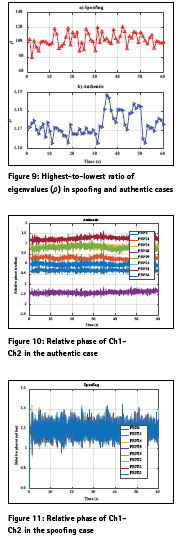
In the post-despreading spatial spoofing detection the IF samples of the array were processed with a GNSS software receiver. The software receiver tracked the first channel data in PLL mode and used the tracking parameters (code, frequency and phase) to wipe-off the second channel data. The relative phase of Ch1-Ch2 can be measured by analyzing the in-phase and quadrature outputs of Ch2. The relative phase of Ch1-Ch2 at the correlator output is a function of the direction of arrival of satellite and relative path delay of the RF chain of Ch1-Ch2. In the spoofing case since all PRNs are arrived from the same direction the phase difference between Ch1 and Ch2 for all PRNs should be the same whereas in the authentic case since the direction of arrival of different PRNs varies the receiver should observe different values for Ch1- Ch2 relative phase. Figure 10 shows the relative phase of Ch1-Ch2 for various PRNs in the authentic case. As shown different PRNs have different relative phase values. In some cases (e.g. PRN 14 and PRN 19) the relative phase of Ch1- Ch2 have similar trend. This is due to the fact that they are located approximately in the same location or due to the inherent cone ambiguity of the linear array the method cannot distinguish signals coming from different angles located on the cone of ambiguity. This issue can be reduced by utilizing a planar array. Figure 11 shows the relative Ch1-Ch2 phase values for the covered spoofing case. As shown all values are overlapped which indicates all of the signals are transmitted form the same location where the covered spoofing attack can be detected.
Conclusions
A covered spoofing scenario was investigated in this paper where the reception of the authentic signals were blocked and the receiver antenna only exposed to the counterfeit signals. As shown the covered spoofing scenarios is relatively easy to implement while the signal quality was preserved. Different signal quality measures including C/N0 Doppler and carrier tracking indicator were analysed. Based on the experimental results provided here the multipath due to signal propagation inside the spoofing case was not a concern. Various single antenna based spoofing detection metrics in the case of covered spoofing attack were analysed. The results revealed that these metrics are not sensitive to the attack and hence cannot be used to detect such spoofing attack. A two-element antenna array was utilized to implement spatial processing in pre-despreading and post- despreading stages of a GNSS receiver. As shown the covered spoofing attack can be successfully detected using antenna array processing.
References
[1] T. E. Humphreys, B. M. Ledvina, M. L. Psiaki, B. W. O’Hanlon and P. M. Kintner “Assessing the Spoofing Threat: Development of a Portable GPS Civilian Spoofer,” ION GNSS 21st. International Technical Meeting of the Satellite Division, Savannah GA, pp. 2314-2325, 16-19 September 2008
[2] B. M. Ledvina, W. J. Bencze, B. Galusha and I. Miller “An In-Line Anti-Spoofing Device for Legacy Civil GPS Receivers” Proceedings of the 2010 International Technical Meeting of The Institute of Navigation, 25-27, San Deigo CA, pp. 698-712, January 2010
[3] A. Jafarnia-Jahromi, “GNSS Signal Authenticity Verification in the Presence of Structural Interference,” PhD Thesis, Department of Geomatics Engineering, University of Calgary, September 2013.
[4] R. G. Hartman and P. Minn “Spoofing detection system for a satellite positioning system” US Patent 5557284, 1995
[5] C. E. McDowell “GPS Spoofer and Repeater Mitigation System using Digital Spatial Nulling”, US Patent 7250903 B1, 2007
[6] M. L. Psiaki, M. L., Powell, S.P., O’Hanlon, B.W., “GNSS Spoofing Detection using High-Frequency Antenna Motion and Carrier-Phase Data,” Proceedings of the 26th International Technical Meeting of The Satellite Division of the Institute of Navigation (ION GNSS 2013), Nashville, TN, pp. 2949-2991, September 2013.
[7] S. Daneshmand, A. Jafarnia, A. Broumandan and G. Lachapelle “A Low-Complexity GPS Anti-Spoofing Method Using a Multi-Antenna Array” in Proceedings of ION GNSS 2012, Nashville TN, 11 pages, 17-21 September 2012
[8] T. E., D. Humphreys, Shepard, J. Bhatti, and K. Wesson “A testbed for developing and evaluating GNSS signal authentication techniques” in IEEE Transactions on Aerospace and Electronic Systems, 15 pages, 2011.
[9] P. F. Swaszek, and R. J. Hartnett “Spoof detection using multiple COTS receivers in safety critical applications” in ION GNSS+ 2013, Nashville, Tennessee, September 2013.
[10] J. Nielsen, V. Dehghanian and G. Lachapelle (2012) “Effectiveness of GNSS Spoofing Countermeasure based on Receiver CNR Measurements” International Journal of Navigation and Observations, vol. 2012, Article ID 501679, 9 pages, 2012.
[11] A. Jafarnia, A. Broumandan, J. Nielsen and G. Lachapelle “GPS Spoofer Countermeasure Effectiveness based on Using Signal Strength, Noise Power and C/N0 Observables” International Journal of Satellite Communications and Networking, vol 30, no 4, pp. 181– 191, July 2012.
[12] A. Jafarnia, A. Broumandan, J. Nielsen and G. Lachapelle “Pre-Despreading Authenticity Verification for GPS L1 C/A Signals,” NAVIGATION, Journal of The Institute of Navigation, Vol. 61, Issue 1, pp 1-11, 2014.
[13] E. McMilin, D. S. De Lorenzo, T. Walter, T. H. Lee, and P. Enge “Single Antenna GPS Spoof Detection that is Simple, Static, Instantaneous and Backwards Compatible for Aerial Applications” Proc. ION GNSS+ 2014, Tampa, FL, Sept. 9-12 2014.
[14] S. Daneshmand, A. Jafarnia Jahromi, A. Broumandan, J. Nielsen and G. Lachapelle “GNSS Spoofing Mitigation in Multipath Environments Using Space-Time Processing,” Proceedings of the European Navigation Conference (ENC2013), Vienna, 23-25 April 2013.
[15] E. G. Manfredini, F. Dovis, and B. Motella “Validation of a signal quality monitoring technique over a set of spoofed scenarios” 7th ESA Workshop on Satellite Navigation Technologies and European Workshop on GNSS Signals and Signal Processing (NAVITEC), pp. 1-7, 2014.
[16] A. Jafarnia-Jahromi, A. Broumandan, J. Nielsen and G. Lachapelle “Pre- Despreading Authenticity Verification for GPS L1 C/A Signals” NAVIGATION, Journal of The Institute of Navigation, Vol. 61, Issue 1, pp 1-11, 2014.
[17] A. Broumandan, A.Jafarnia-Jahromi, S. Daneshmand, and G. Lachapelle “A Network-based GNSS Structural Interference Detection, Classification and Source Localization,” proceeding of ION GNSS+2015 , Tampa Florida, September 2015.
[18] Y. Guo, M. Fan, and M. Kong “Spoofing interference suppression using spacetime process for GNSS receiver,” International Congress on Image and Signal Processing (CISP), Sichuan, China, pp. 1537-1541, Oct 16-18 2012
[19] M. D. Zoltowski, and A. S Gecan “Advanced adaptive null steering concepts for GPS”, Military Communications Conference, MILCOM 95, IEEE, San Diego, CA, USA, , pp. 1214-1218, 5-8 November 1995
[20] C.E. McDowell “GPS Spoofer and Repeater Mitigation System using Digital Spatial Nulling” US Patent 7250903 B1, 7 pages 2007
[21] Meurer, M., A. Konovaltsev, M. Cuntz, C. Hättich “Robust Joint Multi- Antenna Spoofing Detection and Attitude Estimation using Direction Assisted Multiple Hypotheses RAIM,” Proceedings of the 25th International Technical Meeting of The Satellite Division of the Institute of Navigation (ION GNSS 2012), Nashville, TN, pp. 3007-3016, September 17-21, 2012
[22] S. Daneshmand; A. Jahromi, A. Broumandan and G. Lachapelle “A GNSS structural interference mitigation technique using antenna array processing” IEEE Sensor Array and Multichannel Signal Processing Workshop (SAM), Coruna, Spain, pp. 109-112, 22-25 June 2014
[23] S. Daneshmand, A. Jafarnia, A. Broumandan and G. Lachapelle “A Low Complexity GNSS Spoofing Mitigation Technique Using a Double Antenna Array” GPS World magazine, vol 22, no 12, pp. 44-46, December 2011
[24] A. Jafarnia, A. Broumandan, S. Daneshmand, N. Sokhandan and G. Lachapelle “A Double Antenna Approach toward Detection, Classification and Mitigation of GNSS Structural Interference,” Proceedings of NAVITEC 2014, Noordwijk, Netherlands, 3-5 December 2014.
[25] A. Pirsiavash, A. Broumandan and G. Lachapelle “Characterization of Signal Quality Monitoring Techniques for Multipath Detection in GNSS Applications,” Sensors 2017, doi:10.3390/s17071579
The paper was presented at International Technical Symposium on Navigation and Timing (ITSNT) 2017, 14-17 Nov 2017 ENAC, Toulouse, France


 (1 votes, average: 3.00 out of 5)


Leave your response!