| GNSS | |
EGNOS-based Reactive Locator for the European Train Control System
The paper describes a novel train LDS solution based on EGNOS for ETCS |
 |
|
It is generally believed that exploitation of Global Satellite Navigation Satellite System (GNSS) together with advanced mobile communications for signalling and train control will significantly improve safety and efficiency of railway operations. This is especially true for signalling solutions on low traffic lines and also on some long heavy haul lines where previously planned implementations of the European Train Control System (ETCS) with track balises have appeared as economically unrealistic. Moreover, there are currently visions that ETCS solutions based on GNSS will be installed on main corridor and high-speed lines as well.
The very idea of combining satellite navigation and the ETCS for train localization purposes is not new. A mixed train position determination solution by means of ETCS track balises and virtual GPS ones has been already described in the nineties of the last century [1]. Before that, a series of tests focused on train position determination using GPS and DGPS had been performed mainly in the United States and Europe.
On the 2nd March 2011, the European Geostationary Navigation Overlay Service (EGNOS) with its Safety-of-Life (SoL) Service was officially declared available for safety operations in aviation. EGNOS belongs to the family of widearea Satellite Based Augmentation Systems (SBAS), similarly as US WAAS [2], Russian SDCM, Indian GAGAN, etc. In spite of fact that SBAS with its SoL service was originally developed and certified for safety operations in aviation, it also represents a strategic infrastructure for safety-related systems in other modes of land transport [3] – [7].
Safe train Location Determination System (LDS) based on GNSS and intended for ETCS belongs among them. It is mainly due to fact that high investment and operational costs of the ETCS track balises used for safe train position determination discourage from further ETCS expanding not only in Europe, but also worldwide. Therefore, at present, the European Commission, institutions and railway industry strongly support replacement of physical balises with virtual ones based on EGNOS and Galileo. This intention is practically realised within several international ESA and H2020 projects (e.g. 3InSat, ERSAT EAV, STARS, RHINOS), and also within numerous national R&D activities in the individual EU member states.
However, only the efficient exploitation of EGNOS for railway signalling according to specific ETCS safety requirements, TSI, railway CENELEC safety standards [8]- [10], etc. can bring applicable solutions. A clear LDS safety concept fully exploiting characteristic GNSS features within the virtual balise (VB) concept, such as provision of abundant train positions in time, is the basis for derivation of realistic ETCS safety requirements for the EGNOS SoL service. It is evident that rapid and independent diagnosis of excessive EGNOS errors significantly contributes to achievement of the required tolerable hazard rate (THR) for the ETCS virtual balises and also for the GNSS LDS.
Basic safety requirements for the train location determination function based on GNSS were specified within the ESA 3InSat project (2012-2015) [11], [13]. It was found that THR for Signal-In-Space (SIS) should meet 1e-8/ 1 hour (SIL 4) and the maximal confidence interval (CI) in the position domain should not exceed 14 m for the most demanding ETCS operational scenarios. In order to meet the safety requirements, the dual-constellation EGNOS-R (R as railway) interface with composite fail-safety for EGNOS V3 has been proposed [12], [13]. However, multiconstellation/ multi-frequency EGNOS V3 is expected to be available as lately as in 2022 and the current pressure for signalling and train control solutions based on GNSS is continually growing. Moreover, there is still a will to utilise existing EGNOS as it is for signalling and that’s why new ways enabling it are still investigated.
This paper deals with a novel solution enabling to meet very demanding ETCS safety requirements for virtual balise detection, i.e. THR less than 1e-9 per 1 hour and Safety Integrity Level (SIL) 4, using existing single-constellation EGNOS V2 already certified for safety operations in aviation. The solution consists in LDS with the reactive fail-safety architecture based on EGNOS V2 and supported by a newly introduced travelling virtual balise (TVB) concept. Abundant validated LDS position, velocity and time (PVT) data on track sections between static virtual balises have been proposed for rapid diagnosis of virtual balise detection. The rapid and independent LDS diagnosis is critical for the reactive architecture. The TVB is used for justification of the required safety integrity provided by EGNOS. Since standalone EGNOS V2 based on GPS is not able to meet ETCS reliability requirement for onboard unit (MTBF of 3e5 hours) for hard operational scenarios, then Galileo as a second redundant channel of the 1oo2 (one-out-of-two) LDS architecture within EGNOS V3 was proposed to meet this hard operational target.
Way to efficient EGNOS V2/ V3 exploitation in ETCS
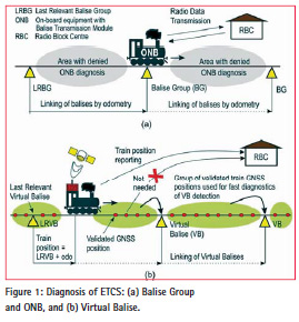
The classical ETCS track balise group, also called information point (IP), which shall be compliant with SIL 4 (λIP of 1e-9/1 hour) [6], determines together with the ETCS on-board balise reader, a so-called balise transmission module (BTM), the absolute position of train. The ETCS odometry (SIL 4) provides the instant speed of train and the relative distance from the last relevant balise group (LRBG) including its CI. The train position, velocity and other data are reported via radio (GSM-R) to the track-side radio block centre (RBC). One of the important odometry functions is called linking of balises via the relative distance measurement. It is in fact the independent diagnosis of balises and on-board unit (ONB) because it enables detection of a deleted (missing) balise, incorrectly inserted balise or an ONB fault.
In case of the virtual balise concept the absolute position of train is determined using the LDS based on GNSS. The instant position of the train is compared with the position of virtual balises whose coordinates are stored in the on-board European vital computer (EVC) and in RBC. If the actual GNSS train position together with the relevant CI match with a virtual balise stored in the database, then the VB is considered as the last relevant virtual balise (LRVB). The odometry together with the track database perform two following functions: 1) diagnosis of the consecutive virtual balises using linking with its direct positive impact on the desirable reduction of the safety integrity requirement for the GNSS LDS – i.e. GNSS THR increasing, and also 2) provision of the relative train position from LRVB if GNSS SIS is temporally unavailable due to SIS service outages or SIS shadowing in a harsh railway environment.
And now it should be answered the question how ETCS can profit from GNSS – where is the main gain. As it is evident from Figure 1(a), the ETCS ONB is able to perform fault diagnosis of physical balise groups (BGs) and also its own diagnosis only in locations of the BGs. It is possible thanks to BG linking because position of next BG with respect to the LRBG position is known to the ONB and the correct BG detection can be validated using a so-called expectation window (ExW). The ExW includes all potential uncertainties due to odometry and BG position errors. However, GNSS LDS is naturally able to perform its fault diagnosis also in the vicinity of virtual balises or on the whole track section between virtual balises, depending on SIS visibility – see Figure 1 (b). It can be utilised for a fully automatic LDS initialization, which is in case of the baseline ETCS with track BG performed in Staff Responsible (SR) mode and the unreliable human factor must be involved in this safety function.
Note: parallel track discrimination in this LDS development phase can be solved by classical means (track circuits, axle counters, balises) or later by GNSS – e.g. two tier augmentation [5] or using future EGNOS with decimetre accuracy.
The abundant GNSS train positions outside of the VB vicinity are not in fact needed under normal operation (after LDS initialization) for train position reporting to RBC because it is provided by means of the relative distance measurement from the LRVB – see Figure 1(b). However it is evident that these abundant GNSS positions together with the odometry data and other techniques can be effectively used for the rapid GNSS diagnosis and it can in final effect lead to significant reduction of safety requirements for the GNSS-based LDS. It opens the door for railway exploitation of current EGNOS V2 in terms of the required LDS safety integrity and also enables to prepare a roadmap for efficient, i.e. safe and reliable EGNOS V3 exploitation in ETCS. It is the major benefit of the above rapid validation of VB for ETCS LDS.
Two following VB failure modes can be specified:
• Virtual Balise Deletion – means an event, when the VB (i.e. virtual IP) was not determined by means of onboard GNSS LDS. It can happen due to: 1) excessive latent LDS error (wrong position), or 2) absence of train position in the GNSS LDS output. In both cases no VB is detected within the ExW provided by the odometry;
• Virtual Balise Insertion – means an event when a wrong virtual balise is determined due to wrong GNSS LDS position.
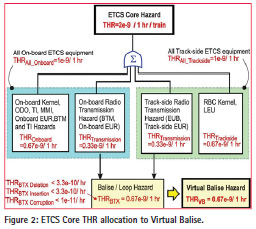
Since both VB failure modes are caused by a wrong GNSS LDS position (i.e. incorrect or no position), and diagnosis for both failure modes is provided by rapid and independent diagnosis in GNSS service volume, then the total THRBTX of 0.67e-9/ 1 hour was taken as THR for virtual balise, i.e. THRVB = 0.67e- 9/ 1 hour – see Figure 2. THRVB will be further used for derivation of the ETCS THR requirement for GNSS, i.e. THRGNSS (THRSBAS). The derivation and justification of THRGNSS for the virtual balise insertion/ deletion is described in the next section.
Novel LDS solution based on EGNOS V2/V3
The SIS Integrity Risk (IR) of 2e-7/150 s is guaranteed by EGNOS V2 for APV-I / LPV- 200 service level [15]. Let’s assume that IR corresponds to hazard rate of 4.8e-6/ 1 hour. There are two following possibilities how to meet the THR for virtual balise detection, i.e. THRVB of 0.67e-9/ 1 hour, by means of LDS based on EGNOS V2. First, EGNOS integrity has to be improved by a suitable technique. Or requirement for EGNOS integrity has to be somehow reduced assuming that the target THR requirement for VB and also for LDS has to be met.
Railway safety-related systems to be compliant with SIL 3 or SIL 4 must ensure that they will remain safe in the event of any kind of single random HW fault. This principle is known as failsafety and can be achieved by means of the following techniques [10]:
• Inherent fail-safety;
• Composite fail-safety; and
• Reactive fail-safety.
Implementation of these techniques not only determines which level of LDS safety will be achieved, but also how efficiently GNSS will be used within the LDS.
Inherent fail-safety allows a safetyrelated function to be performed by a single channel, provided that all the credible failure modes of the channel are not hazardous. It would be very difficult or impossible to make such evidence in case of complex EGNOS and therefore inherent fail-safety is not further considered for the EGNOS-based LDS.
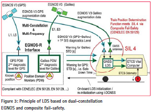
Composite fail-safety allows a safetyrelated function to be performed by at least two independent channels. Hazardous fault in one channel shall be detected and negated in sufficient time to meet the required THR. The fault is detected by the comparison of the output values of these two or more channels, or also by means of an additional independent diagnosis. This technique has been already employed in case of a dual-constellation EGNOS-R interface [12], [13] – see Figure 3. The EGNOS-R (R as railway) was mainly proposed with the intention to improve EGNOS safety integrity and meet the THR requirement for VB detection.
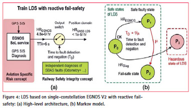
Finally, reactive fail-safety allows a safety-related function to be performed by a single channel, provided its safe operation is assured by fast detection and negation of any dangerous fault. The single channel in itself doesn’t have to meet the required safety integrity. And it is the case of EGNOS within LDS. New reactive LDS solution for VB detection intended for reduction of the safety integrity requirement for EGNOS SoL service is proposed in Figure 4.
It is evident that mere EGNOS employment for LDS within the virtual balise concept is not sufficient since the required VB safety integrity cannot be demonstrated. It is because an average balise group spacing of 400 m in the baseline ETCS is not able to assure sufficient short time to fault detection and negation TD to meet the required safety target (THRVB = 0.67e-9/ 1 hour). Even if the spacing between two consecutive static virtual balises would have been shortened, then it would not have been still possible to distinguish between two adjacent VBs, because they could fall into one ETCS ExW. To solve this problem a non-static VB, a so-called travelling virtual balise (TVB), was newly introduced into LDS concept based on EGNOS V2. It is demonstrated below that the TVB concept together with the reactive LDS 1oo1 architecture (one-out-of-one with diagnostics) is able to meet the THR requirement for VB.
LDS with reactive failsafety based on EGNOS
The existing single-constellation EGNOS in itself can be considered as a system with reactive fail-safety, because the safety function is performed by the GPS and its correctness is checked by the EGNOS infrastructure.
Nevertheless, the standalone EGNOS is not yet able to meet the ETCS SIL 4 requirement for train position determination. Excepting this the position determination function must also meet the required SIL/THR in case of local effects, such as multipath, EMI, spoofing, etc. against which EGNOS does not protect. That’s why the EGNOS fault diagnosis must be completed with an additional independent fault diagnosis realised e.g. using safe ETCS odometry (SIL 4), 3-dimensional track database (SIL 4) and other relevant fault detection techniques.
The high-level architecture of the reactive LDS is depicted in Figure 4 (a) and the corresponding Markov model of the LDS in Figure 4 (b), where HREGNOS – hazard rate of EGNOS per 1 hour, HRDiag – hazard rate of EGNOS independent diagnosis, μ – rate of diagnosis and fault negation. The following four system states are defined for the model:
• P0 – Fully functional LDS state: both EGNOS and independent EGNOS diagnosis work well according to the specifications;
• P1 – Safe faulty LDS state: EGNOS is faulty and rapid diagnosis is functional;
• P2 – Fail-safe state of the LDS: EGNOS fault was detected and negated;
• P3 – Hazardous LDS state: Independent diagnosis of EGNOS is faulty. Note: Although EGNOS is functioning properly according to the specifications, the LDS is in a dangerous state.
The time (t) dependent probabilities corresponding to the above states are obtained from the Markov model solution [19]. From viewpoint of LDS safety design, the most important is P1(t), which is the safe faulty state probability in case of GNSS/EGNOS fault. The corresponding hazard rate per 1 hour long mission can be expressed as [19]
![]()
where TD (i.e. 1/ μ) is time to fault detection and negation, which is also sometimes called safe down time (SDT) [10]. Equation (1) is used for justification of the EGNOS integrity performance for ETCS LDS in the next section.
Travelling Virtual Balise
The classical ETCS requires both track balises and on-board equipment (ONB) for safe train position determination. On the other hand GNSS estimates the position on board of train. Let us assume that λONB is the rate of occurrence of ONB being unable to detect a correctly working ETCS information point (IP). If linking of IPs is active, then the duration of ONB failure corresponds to the time interval TL between two successive IPs marked as linked. Further if the average speed of train is v and the linking distance DL, then the probability of ONB failure causing the IP deletion is
![]()
There is no safety requirement in respect of not being able to detect an information point when IP linking is active [6]. As lately as two expected consecutive IPs announced by linking are not detected by on-board in the ExW, measured from the Last Relevant Balise Group (LRBG), the on-board vital computer shall consider the linking command of the second IP as a command to apply the service brake. Then the hazardous failure rate of ONB corresponding to the deletion of any IP met during 1 hour long mission is
![]()
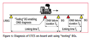
In order to check the ONB functionality even before the detection of a regular and properly working BG by the ONB, an additional hypothetical “testing” BG can be placed on the track ahead of the regular BG in the direction of movement from the LRBG – see Figure 5. A much shorter ONB failure duration TD is achieved in this case. Then (2) can be then modified as
![]()
and the corresponding ONB hazardous failure rate per mission (1 hour) is
![]()
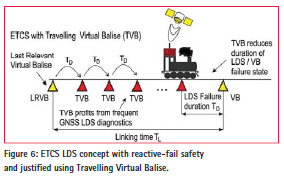
The hazardous ONB failure rate (5) due to IP deletion can be thus reduced with respect to (3) significantly. It is evident that installation of the additional “testing” BGs on a track would be very inefficient. Nevertheless, the reactive fail-safety principle can be easily implemented in case of the GNSS LDS. The “testing” BG is simply replaced by a so-called travelling virtual balise (TVB), as it is depicted in Figure 6.
The TVB is equivalent to LRVB from viewpoint of safety integrity because it is a validated GNSS train position by the independent diagnosis. The TVB arises from the LRVB as a subsequent validated train GNSS position generated just after LRVB is detected and further travels to the next virtual balise location in a given direction of movement. The TVB can also originate on a track section between VBs during LDS initialization.
The detection function of the presence of an information point (IP) by ETCS onboard unit (ONB) is a critical function and this function is the most critical when IPs are employed in scenarios where linking is not used. It is e.g. during ONB initialization in SR mode or during entry into an ETCS area from unfitted area when wrong IP can be inserted or IP can be deleted. The ETCS THR requirement for GNSS must be derived using these scenarios considering that VB insertion can cause a more dangerous situation than VB deletion.
It is evident that the TVB can be utilized for the LDS diagnosis of the next VB from viewpoint of VB deletion or insertion failure modes in the same manner as the hypothetical static “testing“ BG is used in Figure 5. The ETCS THR requirement for GNSS (i.e. THRGNSS) can be determined for the LDS startup from the THR requirement for VB deletion or insertion per mission, i.e. THRVB of 0.67e-9 hour-1, as
![]()
where TD is the duration of GNSS hazardous failure defined as the time interval between the two consecutive linked TVBs or linked TVB and next VB.
The SIS IR of 2e-7/150 s for Precision Approach (PA) including LPV-200 operations is required in the vertical direction. Excepting this the SIS IR of 1e-9/150 s in the horizontal/ lateral (one dimensional) direction shall be also met for the aviation PA operations. It seems that the integrity (i.e. guarantee) of accuracy in the horizontal plane or in the track direction would be sufficient for signalling in case of the reactive LDS architecture. Nevertheless, three dimensional (3D) track map appears as an effective means for the independent diagnosis of EGNOS, and therefore the IR of 2e-7/150 was conservatively selected for signalling. The corresponding EGNOS SIS hazard rate is approximately 4.8e- 6/ 1 hour. Then the allowed duration of GNSS/EGNOS failure can be estimated as
![]()
The horizontal alert limit (HAL) of 40 m and VAL (vertical AL) of 35 m is required for LPV-200 operations, where the pilot’s decision height is 200 feet (60 m) above the runway. The actual WAAS/ EGNOS accuracies (95%) in horizontal/ lateral and vertical directions are typically better than 1.1 m and 1.5 m, respectively. If SBAS receiver with an output rate of 10 Hz will be used, then all the above calculated value of TD is realistic.
EGNOS V3 for LDS reliability improvement
LDS based on EGNOS shall meet excepting the required safety integrity also a high reliability for ETCS onboard unit, which is specified as mean time between service hardware failures MTBF-SONB of 3e5 hours [16]. Reliability of the proposed LDS solution can be evaluated using continuity attribute of the applied EGNOS service level.
Continuity, or reliability, is the ability of a system to function within specified performance limits without interruption during a specified period, i.e. the continuity time interval t, which represents the most critical phase of operation or whole operation in aviation. The duration of the most critical phase is 15 s for APV-I/ LPV-200 operations [15]. Assuming the service is functioning at the beginning of the operation, then the probability that it is still functioning is [17]:
![]()
This is the standard expression for reliability and excludes scheduled outages (i.e. uses MTBF) assuming that planned outages will be notified and the operation will not take place. If MTBF is much greater than t, then (8) can be approximated to
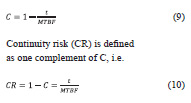
Equation (10) can be utilised for calculation of MTBF for specific EGNOS SoL service level.
The ICAO requirement for SIS CR for APV I approach is 8e-6/ 15 seconds. It corresponds according to (10) to MTBF of 520.8 hours. It is much less than e.g. the required ETCS mean time between service hardware failures MTBF-SONB of 3e5 hours, which is specified for onboard equipment. It is evident that the aviation CR requirement for single constellation EGNOS V2 is unable to meet the ETCS reliability requirement using the LDS 1oo1 architecture.
Let’s consider now a dual-constellation LDS (GPS and Galileo) based on EGNOS V3 as a dual-channel redundant system with 1oo2 architecture. Then MTBF of the 1oo2 LDS architecture can be expressed as [19]
![]()
If MTBF of 520.8 hours for both GPS and Galileo channels within EGNOS V3 is assumed, then for t=1 hour eqn (11) yields MTBF1oo2 of 2.7e5 hours. It means that the LDS based on dualconstellation EGNOS V3 with the reactive fail-safety architecture and TVB is able to practically meet the required MTBFSONB for the ETCS on-board equipment.
Conclusion
This paper describes a novel train LDS solution based on EGNOS for ETCS. The solution consists in LDS with reactive fail-safety based on EGNOS V2 or EGNOS V3, which is further combined with a newly introduced travelling virtual balise (TVB) concept.
It has been demonstrated that the required THR for virtual balise of 0.67e- 9/ 1 hour can be met using the reactive LDS structure with single-constellation EGNOS V2. The TVB has been employed within the ETCS virtual balise concept to justify use of EGNOS from viewpoint of the required LDS safety integrity. The LDS solution contributes to the harmonization of the aviation and railway safety concepts based on EGNOS, because the required safety integrity targets in both transport modes can be met by singleconstellation EGNOS V2. Galileo as a second constellation within EGNOS V3 can be then used for reliability and availability of integrity improvement via the redundant 1oo2 LDS architecture.
Acknowledgement
This work was supported from the European H2020 research and innovation programme within the RHINOS project (2016-2017).
References
[1] B. J. Sterner, “On the Method of combining GPS and ETCS for Localization Purposes”, The European Railway Research Institute (ERRI), Draft of the 8th May 1998, 6 pages.
[2] RTCA DO-229D – “Minimum operational performance standards for GPS WAAS Airborne Equipment”, RTCA Inc., Washington, D.C., 2006.
[3] S. Pullen, T. Walter, and P. Enge, “Integrity for Non-Aviation Users. GPS World,” July, 2011, pp. 28–36.
[4] A. Neri, S. Sabina, F. Rispoli, and U. Mascia, “GNSS and odometry Fusion for High Integrity and High Availability Train Control Systems,” ION GNSS+ 2015, Tampa, September 14-18, 2015, 11 pages.
[5] Neri, A., Vegni, M. and Rispoli, F.: A PVT Estimation for the ERTMS Train Control Systems in presence of Multiple Tracks. Proc. of ION GNSS 2013, September 16-20, 2013, Nashville, TN, USA.
[6] “ETCS/ERTMS – Class 1, ETCS Application Levels 1 & 2 – Safety Analysis, Part 3 – THR Apportionment,” SUBSET-088 Part 3, ISSUE: 2.3.0, DATE: 02-04-2008, 91 pages.
[7] “ETCS/ERTMS Safety Requirements for the Technical Interoperability of ETCS in Levels 1 & 2”, SUBSET-091, ISSUE: 3.3.0, DATE: 2014-05-08, 51 pages.
[8] “EN 50126 Railway Applications: The Specification and Demonstration of Dependability Reliability, Availability, Maintainability and Safety (RAMS),” CENELEC European standard, 2002.
[9] “EN 50128 Railway Applications: Communications, signalling and processing systems – Software for railway control and protection systems”, CENELEC European standard, 2003.
[10] “EN 50129 Railway Applications: Safety-related electronic systems for signalling,” CENELEC European standard, 2003.
[11] A. Filip and F. Rispoli, “Safety concept of GNSS based train location determination system SIL 4 compliant for ERTMS/ETCS,” Proceedings of ENC GNSS 2014, Rotterdam, April 2014, 15 pages.
[12] A. Filip and F. Rispoli, “SIL 4 Compliant Train Location Determination System Based on Dual- Constellation EGNOS-R for ERTMS/ ETCS,” Proc. of the International Symposium on Certification of GNSS System (CERGAL 2014), Dresden, Germany, July 8 – 9, 2014, pp. 109-114.
[13] A. Filip, “Multi-Constellation Railway SBAS Interface: A Common Platform For Advanced Signalling Compliant With SIL 4 World-Wide,” Proceedings of the International Heavy Haul Association 2015 conference (IHHA), Perth, Australia, June 21-24, 2015, 10 pages.
[14] T. Lovric, J. Gülker, “Singe Channel ATP Architectures, a new Trend in Europe?,” WCRR 2001, Köln, November 25-29, 2001, 9 pages. http://www.uic.org/cdrom/2001/ wcrr2001/pdf/sessions/3_5/040.pdf
[15] EGNOS Safety of Life (SoL) Service Definition Document, GSA, 2015, ISBN: 978-92-9206-025-1, 64 page.
[16] ERTMS/ETCS RAMS Requirements Specification Chapter 2 – RAM, Version-6, Reference EEIG : 96S126, UIC, 30/09/98, 83 pages.
[17] e-NAV2 / 07 / 02 Continuity requirements. Document available at: https://imo.amsa.gov.au/ialaaism/ e-nav/e-nav2/eNAV2-07- 02ContinuityRequirements.pdf
[18] GNSS Rail Advisory Forum: REQUIREMENTS OF RAIL APPLICATIONS, UIC, May 2000, 29 pages.
[19] Filip, A., “Efficient use of multiconstellation EGNOS for the European Train Control System,” Proceedings of the 2016 European Navigation Conference (ENC GNSS 2016), Helsinki, May 30 – June 2, 2016, 9 pages.


 (No Ratings Yet)


Leave your response!