| Mapping | |
Determination of surface characteristics and alteration of Koru mining area by UAV photogrammetry
In this study, a low-cost UAV-based remote sensing approach reveals high-resolution digital surface models has been utilized for surface characterization |
 |
|
 |
|
 |
|
Introduction
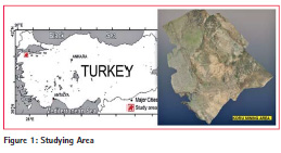
Study Area
The study area is located near the Koru (Lapseki/Çanakkale) village in northeastern part of the Biga Peninsula. Koru deposit is hosted by volcanic rocks which are directly related to economically significant mineralization such as Pb-Zn. This deposit is shaped by Tertiary volcanic units, including rhyolitic lava and tuffs.
UAV-based Remote Sensing for Geological Classification
Many scientists have performed UAVbased photogrammetry and remote sensing for many decades. As the first motorized UAV photogrammetry workings, fixed wing remote controlled air vehicles have been developed in 1970s (Przybilla and Wester-Ebbinghhaus, 1979). The first highresolution digital elevation models was produced by Eisenbeiss et al. (2005) using autonomously UAV helicopter. Nowadays, there are many other UAV-systems for using (Jütte, 2008, Gomez-Lahoz and Gonzalez-Aguilera, 2009, Fotinopoulos, 2004, Aber et al., 2002). The use of high resolution digital photogrammetry based on UAV technology for classifying of surface geology has been tested in this study.
UAV SYSTEM
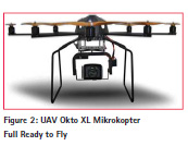
Eight-Rotor Oktokopter UAV
When compared to conventional helicopters, quad-rotor systems are more stable in flight with reduced vibration and have the mechanical advantage of not requiring a large, variable pitch rotor-unit. Our in-house developed quad-rotor system is stabilized by inertial measurement units (IMU), including three acceleration sensors, three gyroscopes, a three-axis compass, pressure sensor, and is regulated by basic PID (proportional integral differential) loops. A quad-rotor open source project (Mikrokopter, 2009) has been used and improved by modifications of the software and the electronic circuit, in order to comply with the requirements for landslide studies. Technical data of Oktokopter XL can be summarized as follows:
• Dimensions 73x73x36 (BxLxH)
• Payload: recommended max. payload = 2,500 g
• Max. altitude: Line of sight (several 100 m)
• Max. distance: Line of sight (several 100 m)
• Flight time: max. 45 min at
full battery load (30 Ah)
• Realistic flight time: 18-28 Min (10 Ah) [See tables below]
• Telemetry with speech: Voltage, capacity, current, altitude, distance, direction, speed and temperature
Camera-systems
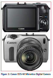
For optimum flight time, the eight-rotor UAVs should be equipped with lightweight low-cost digital compact camera, which support manual camera settings. In this study, we used Canon EOS-M Mirrorless Digital Camera (see Figure 3). For all flights, the camera settings were fixed to ISO 200 at F2.8 and a focus of 18 mm. These settings enabled an average shutter speed of 1/800s which was necessary to avoid blurred photographs.
Specifications:
• Type: Digital single-lens nonreflex, AF/AE camera
• Image Format: 22.3 x 14.9 mm (APS-C size)
• Compatible Lenses: Canon EF-M lenses, Canon EF lenses including EF-S lenses (35mm-equivalent focal length is approx.,1.6x the lens focal length)
• Lens Mount: Canon EF-M mount (Canon EF-M lenses can be mounted directly to the camera. Canon EF lenses (including EF-S lenses) can be attached by using the optional Mount Adapter EF-EOS M.)
Lens System:
• Type: Wide-angle lens – 22 mm – F/2.0 STM Canon EF-M
• Focal Length Equivalent to 35mm Camera: 35 mm
• Focus Adjustment: Manual/Automatic
• Min Focus Range: 5.9 in
• Max View Angle: 63.5 degrees
• Lens Construction: 6 groups/ 7 elements
• Filter Size: 43 mm
• Lens System Mounting: Canon EF-M
Camera calibration scheme
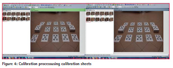
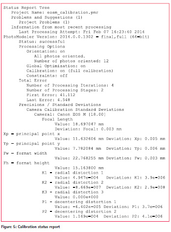
Camera calibration determines information about the camera that improves accuracy in subsequent studying projects. Calibration process calculates the camera’s focal length, lens distortion, format aspect ratio, and principal point. The resulting calibration data file can be saved on disk for use in all the projects that involve photographs taken by that camera. High accuracy works, e.g., digital surface modeling, require a well calibrated camera. Various calibration algorithms have been developed and improved over a period of more than decades. Some automatic camera calibrators are fully automated and very accurate, plus they are included at no extra charge as part of the basic software package. It is designed to be practical to use and suitable for the broadest range of automatic camera calibrator users. In this study, we used PhotoModeler’s camera calibrator. To do
it, we have performed the field calibration project using calibration sheets including the coded targets (see Figure 4). The calibration status report is given in Figure 5.
Image acquisition
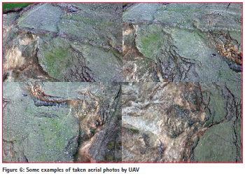
A set of UAV-acquired photographs covering the whole mining area in Koru (Lapseki/Çanakkale) village were taken. The achievable altitude over ground was in the range between 40 m and 70 m. All photographs were taken manually using shooter of remote controller and First Person View (FPV) flying mode. In a first in-situ flight planning step, the desired area and suitable locations for starting and landing were chosen. Then the quadrotor was launched to the maximum flight altitude of about 70 m. At this location, the UAV was hovered for about 45 seconds. Note that the pilot initiated vertical landing. After each flight, we downloaded and checked the covered area of the acquired photographs on-site (see Figure 6).
Digital surface model processing
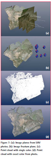
In order to produce digital surface model, we processed the data in PhotoModeler Scanner software. The photographs of the entire mining area (manually preselected by criteria like image quality and covered area size) were computed to digital surface models in 4 sub-areas. First, all photographs were processed to get the image planes from the UAV photographs and camera positions [see Figures 7 (a) and (b)]. Then, these data were supplied to the patch based multi-view stereo procedure of the software that finally computed a dense point cloud for all supplied photographs.
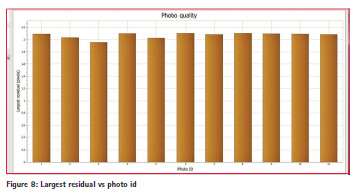
Thereby, we obtained 3D digital surface model including point cloud with single color and point cloud with exact color from the photographs as seen in Figures 7 (c) and (d). Furthermore, the largest residual for each photo in Figure 8 clearly shows the photo quality production of digital surface models during software process.
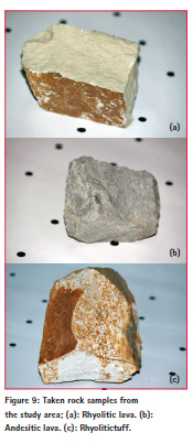
In the study area, we get some rock samples from the region. You can see them from Figure 9. The photos of rhyolitic lava, andesitic lava and rhyolitic tuff are given in Figures 9 (a), (b) and (c), respectively. A histogram is a graph that
can help you evaluate a digital image. Histograms can be found on digital cameras and in computer software. We used Photomodeler software. From the RGB histograms of these rocks, the values are regionally averaged for
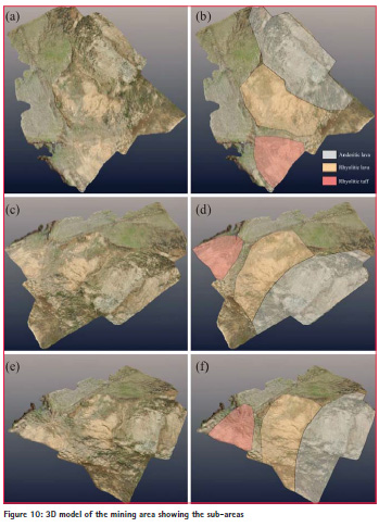
the actual RGB colors (Lichti, 2005, Bachmann et al., 2010, Buckley et al., 2010). The average RGB values of the rocks are obtained. Figures 10 (a), (c) and (e) show the 3D surface models using UAV-remote sensing from three different aspects. Finally, we searched for 3D surface models according to the averaged RGB colors of sampled rocks in order to classify surface characteristics of the study area. The matched areas are covered with related colors. Figures 10 (b), (d) and (f) indicate good matching for landing classifications. Moreover field observations also confirm this.
Conclusions
In this study, for surface characterization, we showed that a low-cost UAV-based remote sensing approach reveals highresolution digital surface models. To do it, terrestrial and aerial photographs were taken and their RGB values were
compared with each other. Finally, the matched areas, e.g., rhyolitic lava, andesitic lava and rhyolitic tuff were successfully determined, classified and zoned. We propose to use the UAV remote sensing for classifying geological characterization. As for future work, we plan to extend this approach using geological spectrometer tools for increasing inner reliability of the used approach.
Acknowledgments
This paper is an extended and reviewed version of the study that was presented at the FIG Congress 2014, Engaging the Challenges, Enhancing the Relevance, Kuala Lumpur, Malaysia, 16 – 21 June 2014. This work partly was supported by the Scientific and Technological Research Council of Turkey (TUBITAK) with Project Number 112Y336.
References
Bachmann, C.M.,Nichols, C.R., Montes, M.J., Li, R.-R., Woodward, P., Fusina, R.A.,Chen, W., Mishra, V., Kim, W., Monty, J., Mcilhany, K., Kessler, K., Korwan, D.,Miller, W.D., Bennert, E., Smith, G., Gillis, D., Sellars, J., Parrish, C., Schwarzschild,A., Truitt, B., 2010. Retrieval of substrate bearing strength from hyperspectral imagery during the virginia coast reserve (VCR’07) multi-sensor campaign. Mar. Geodesy 33 (2-3), 101–116.
Buckley, S.J.,Enge, H.D., Carlsson, C., Howell, J.A., 2010. Terrestrial laser scanning for use in virtual out crop geology. Photogram. Rec. 25 (131), 225–239.
Eisenbeiss, H.,Lambers, K., Sauerbier, M., (2005), Photogrammetric recording of the archaeological site of Pinchango Alto (Palpa, Peru) using a mini helicopter (UAV). In: Proc. of the 33rd CAA Conference, Tomar, Portugal.
Fotinopoulos, V., (2004), Balloon photogrammetry for archaeological surveys. In: International Archives of the Photogrammetry, Remote Sensing and Spatial Information Sciences, XX ISPRS Congress, Istanbul, Turkey, XXXV-B5, pp. 504-507.
Gomez-Lahoz, J. and Gonzalez-Aguilera, D., (2009), Recovering traditions in the digital era: the use of blimps for modelling the archaeological cultural heritage. Journal of Archaeological Science, 36(1), pp. 100-109.
Jütte, K., (2008), Vergleichverschiedener low-cost Luftbildaufnahme system esowie Einsatzvon Drohnen: Grenzenund Möglichkeiten. In: Bayerische Land esanstaltfür Waldund Forstwirtschaft. Der gepixelte Wald – Fachtagungzur Forstlichen Fernerkundung
Lichti, D.D., 2005. Spectralfiltering and classification of terrestrial laser scanner point clouds. Photogram. Rec. 20 (111), 218–240.
Mikrokopter Drohne (2009) Robin Schneider.
Przybilla, H.-J. andWester-Ebbinghaus, W., 1979. Bildflug mit ferngelenktem Kleinflugzeug. Bildmessungund Luftbildwesen, Zeitschriftfuer Photogramme trieund Fernerkundung, 47(5), pp. 137-142.


 (3 votes, average: 3.67 out of 5)


Leave your response!