| Mapping | |
Continuous high precision navigation
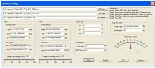
LCIKF provides a graphical user interface for data file selection and the integration Kalman filter tuning, as in Fig. 4, where the initial position is set from the average of static GPS position during the pre-set period of time, and the tilt angles are obtained from the static accelerometer readings, and the initial heading is obtained from the magnetometer readings. The lever-arm vector refers to the vector from the INS mass center to the GPS antenna’s phase center. The user interface allows the user to input the lever-arm with respect to the Body frame (B-frame).
Fig.4 Parameter setting dialog box
3. Design of the system
3.1 Tsync accuracy
The techniques for multisensor time synchronisation can be categorised into two types – the analogue domain and the digital domain. For analogue domain time synchronisation, the analogue signals from the inertial sensors are sampled under the control of its internal clock, which may be aligned with a standard time through the input pulse-per-second (PPS) signal output by a GPS receiver. Time synchronisation is implemented at the stage when the signal is converted from analogue to the digital form. The signal transmission lag can be reduced to a minimum with the analogue domain implementation. However, many applications require an off-the-shelf INS product which has implemented the A/D conversion internally based on its own free-running system clock and, in most cases, it operates in the absence of an external PPS signal. Such an INS packages the digital messages and sends them out through an interface to the outside world. Compared to the analogue domain implementation the main advantage of the digital domain implementation is its flexibility to support a wider range of INS and GPS devices using the same integrating platform.
NavExplorer uses an FPGA to implement time synchronisation in the digital domain. Assuming the PPS transmission delay is small enough that it can be neglected, the sampling tags time-marked by the 3DM-GX2’s internal clock represents the fraction of the time when the data is sampled. Because the moment of PPS time issued at the GPS receiver is known, the accurate INS sampling time in the GPS time-frame can be derived by a combination of the PPS time and the INS time [4]. The result can be expected to have a high accuracy because the PPS time is accurate to the one tenth of nanosecond level, and the INS internal clock is also stable during two PPS pulses.
The INS data has a transmission delay when it arrives at the FPGA data logger. This delay can be estimated using the method described above. A typical delay of the 3DM-GX2 is shown in the Fig. 5, from which an average delay of 2.97ms can be computed.
Fig. 5 Transmission delay of the 3DM-GX2
3.2 Gyro biases
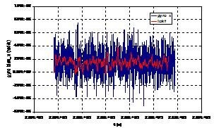
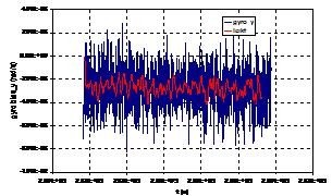
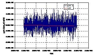
For MEMS gyros, removing the average of the static gyro outputs can improve the accuracy of the attitude solution. Results from testing show that the LCIKF can capture the gyro biases adequately, as indicated in Fig. 6. The raw gyro output is shown as blue lines and the LCIKF’s estimate of the gyro biases is shown as red lines. From Fig. 6 it can be seen that the LCIKF can track the average of the gyro outputs for all 3 axes.
Fig. 6 Gyro outputs and estimate of gyro biases
3.3 Lever-arms
The hardware components of a mobile mapping system will typically be mounted at different physical locations on the host vehicle. The offset between the phase centre of the GPS antenna needs to be compensated for so that the integrated position is INS mass-centred. The LCIKF allows the input of the lever-arm between the INS and GPS, which is then applied to the integration Kalman filter:
3.4 Quality control
Although the velocity flag indicates the velocity of the BD950 is calculated from the Doppler measurements, it has been found that the velocity could contain large jumps during the integer ambiguity procedure when the RTK-GPS radio link is connected. Therefore the LCIKF must have a mechanism to check the quality of velocity measurement. One method is to start feeding the GPS solution into the integration Kalman filter after the integer ambiguities are fixed. However this arrangement is not practical, especially when the system is operating in an area where no RTK-GPS signals are available. An additional Kalman filter is then applied in the LCIKF to monitor the quality of the GPS solution.
In addition to the abnormal jumps in velocity, the position accuracy levels are used to set up the R matrices of the Kalman filters. The noise level of the GPS position and velocity can be manually input or automatically calculated in the LCIKF.
. Institute for Information Industry mobile mapping system
By integrating the NavExplorer with the PGR Ladybug panoramic camera and Multiple SICK laser scanners, a mobile mapping system has been developed at the Institute for Information Industry for the Taipei 3D Urban Reconstruction. NavExplorer generates position data for precise 3D object geo-referencing even when the host vehicle is driven in a tunnel or operates in an environment of frequent GPS outages. Fig. 7 shows the I3 mobile mapping system mounted on a car, where the NavExplorer (the small white box) is installed behind the GPS antenna. Both are connected with yellow cables.
Fig. 7 Mobile mapping system developed at the Institute for Information Industry
5. Road tests
5.1 Tests in Sydney
The RTK-GPS correction signals will cover most of suburban Sydney after the state-wide CORS network is fully operational. However, there could be no RTK-GPS corrections available unless a local reference station is temporarily setup in the test area. Therefore, the system operated in non-RTK mode for road tests in Sydney. The tests aimed to study the performance of the NavExplorer when there was serious multipath, or during GPS outages, or combination of both.
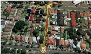
Fig. 8 shows the GPS/INS integrated solution even when the GPS ‘jumps’ off the road because of the effect of multipath in a test that was conducted in the suburb of Rockdale on 26 November 2009. The smooth red line is the GPS/INS integrated solution, and the yellow line is the GPS-only solution distorted by the multipath.
Fig.8 Effect of GPS multipath, GPS/INS(red) vs GPS-only (yellow)
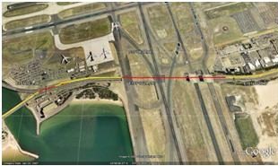
Fig. 9 shows that the GPS/INS integrated solution can bridge the 35s GPS outage through the Sydney airport tunnel in a test on 26 November 2009. It can be seen that the GPS/INS integrated solution (red line) has output in the tunnel whereas the GPS solution (yellow line) is lost. The integrated solution seamlessly matches the GPS solution when the GPS solution becomes available again once outside of the tunnel. Before entering the tunnel, the vehicle was driven under a bridge caused a GPS outage of 6s. It can be seen that this GPS outage has also been smoothly bridged by the integrated solution.
Fig. 9 Bridging the GPS outage through the Sydney airport tunnel, GPS/INS (red) vs GPS-only (yellow)
Fig. 10 shows the GPS/INS integrated solution in a test conducted on 25 November 2009 on the UNSW campus, where the GPS suffers from both frequent outages and the effects of multipath caused by trees and buildings. It can be seen that the GPS/INS integrated solution (red line) is quite smooth during the whole test. It can not only smooth out the multipath from the GPS-only solution (yellow line) but also smoothly bridges the GPS outages.
Fig. 10 Test on UNSW campus of combination of multipath and GPS outages, GPS/INS (red) vs GPS-only (yellow).
5.2 Tests in Taipei
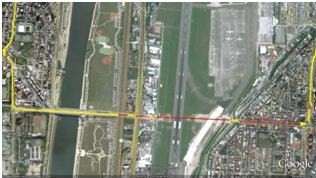
The test was conducted in Taipei on 1 June 2010. In the test the vehicle with the mobile mapping system was driven through a tunnel of length 600m. The NavExplorer’s position is plotted in red on Google Earth in Fig. 11. The GPS-only solution is in yellow.
Fig. 11 shows the track of a test with four GPS outages with lengths 5s, 9s, 36s, and 55s. It can be seen that the integrated solution seamlessly bridges all of these GPS outages.
Fig. 11 Test in Taipei with GPS outages,
GPS/INS (red) vs GPS-only (yellow)
6. Concluding remarks
An inexpensive integrated positioning device has been built for the I3 mobile mapping system. Tests conducted in both Sydney and Taipei demonstrate that the integration of RTK-GPS and MEMS inertial sensors can provide continuous position data in difficult environments with sufficient accuracy.
Further tests will compare the NavExplorer solution with a solution of a higher accuracy.
References
[1] Grejner-Brzezinska, D.A. Mobile Mapping Technology: Ten years later, Part II. Surveying and Land Information Systems, 61(3), 2001, pp. 83-100.
[2] N. El-Sheimy N. An Overview of Mobile Mapping Systems, from Pharaohs to Geoinformatics, FIG Working Week 2005 and GSDI-8, Cairo, Egypt April 16-21, 2005.
[3] El-Sheimy, N. and Niu, X. The Promise of MEMS to Navigation Community. Inside GNSS, March/April Issue, 2007, pp. 46-56.
[4] Li, Y., Mumford, P., and Rizos. C. Seamless Navigation through GPS Outages – A Low-cost GPS/INS Solution. Inside GNSS, July/August, 2008, pp.39-45.
My Coordinates |
EDITORIAL |
|
News |
INDUSTRY | LBS | GPS | GIS | REMOTE SENSING | GALILEO UPDATE |
|
Mark your calendar |
MARCH 2011 TO NOVEMBER 2011 |
Pages: 1 2








 (3 votes, average: 1.67 out of 5)


Leave your response!