| Mapping | |
Accuracy maintenance method for mobile mapping system data at GPS invisible area
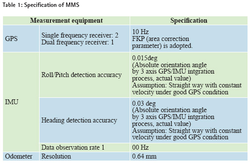
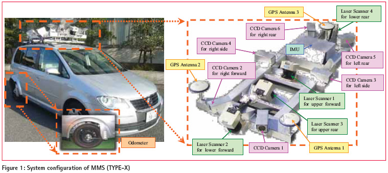
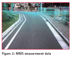
Roads are improved and maintained depending on its roles such as transport routes, minelayers of lifelines, refugee roads at disaster and also needs of users. To improve the roads safety and convenience, road authorities need the data to be used to comprehend 3D shape of the road space and its deformation quickly and accurately. Recently, approaches in the fileld of the maintenance of topographic map data have been improved significantly in Japan. The typical advance is threedimensional measurement of road space using Mobile Mapping System (MMS). Measurement accuracy of the MMS data is highly dependent on GPS satellite constellation, the number of satellites and the signal acquisition situation. While enough GPS satellite signals are captured, the absolute accuracy of the position i.e. latitude, longitude and altitude is accomplished less than 10cm. However there are so many GPS invisible area in the geospatial space such as urban and mountainous area in Japan where high accurate MMS data can not be achieved. It is expected that maintenance of topographic map can be improved efficiently and secondly use of map data in various purpose is prospected if the MMS measurement data in such area can be improved. In this paper, from these perspectives, accuracy investigation of Land Mark Update (LMU) which corrects MMS vehicle position utilizing ground control point was carried out and depending on this result development of accuracy maintenance method in GPS invisible area was considered. Established accuracy maintenance method can be expected that it contributes to common use of MMS and the rapid and steady supply of national infrastructure data. General description of MMSMMS developed by Mitsubishi Electric Corporation Obtains its position and orientation accurately by 3 GPS antennas which allocated as triangle constellation, IMU and odometer. Each collected laser point is given geographical coordinates and superimposed onto imagery captured simultaneously. By using the MMS data, very accurate road 3D spatial information can be obtained. In Fig.1, the system configuration of MMS (Type-X) and in Fig2., collected MMS measurement data(laser point cloud and imagery) are displayed.The specification of position and orientation measurement equipment of MMS are listed in Table.1.
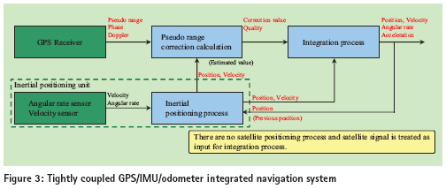
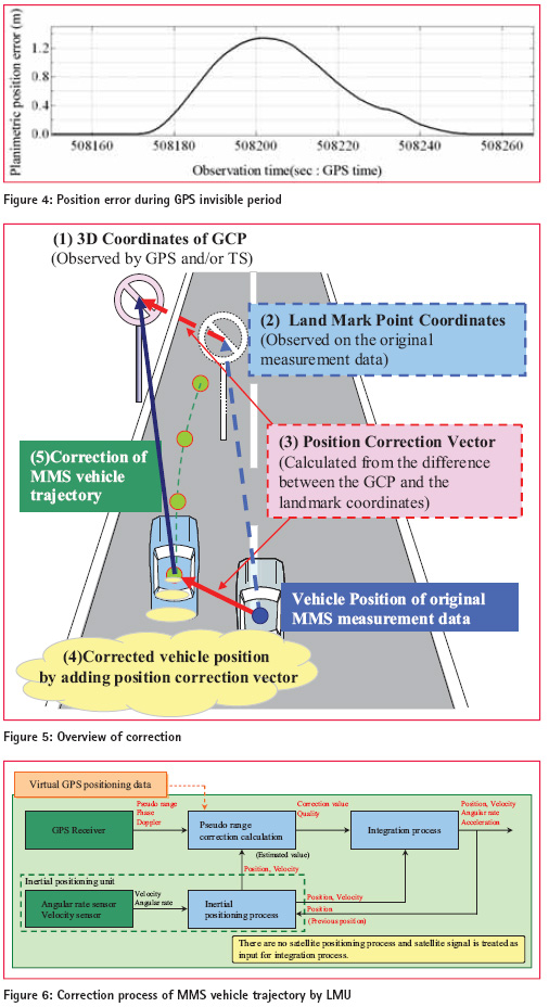
The satellite positioning and the inertial positioning are tightly coupled and constitute Kalman filter of 24th order such as position, orientation, IMU and odometer error. The block diagram is shown in Fig. 3. In the tightly coupling system pseudo range information can be reflected even there are only few visible GPS satellites available and it is effective to the positioning in the urban areas where GPS satellite is visible and/or invisible. Odometer is functioning as a part of velocity sensors of an inertial positioning part. Establish of mapping procedure using MMS and its problemsEstablish of mapping procedure using MMS An effort of topographic mapping by using MMS was started in 2008 as an internal project in Pasco Corp. and since then, accuracy investigation of MMS measurement data and establishment of MMS operation manual have been carried out and compleated with successful results. In 2010 MMS was employed in the firstever public mapping project to update road administration map of Toyonaka City in Osaka prefecture. The result of this project was checked by the Japan Association of Surveyors and certified as public mapping result by GSI (Geospacial Information Authority of Japan) after its evaluation. Problem at satellite invisible area In case of MMS, GPS, IMU and odometer data are integrated to process precise vehicle position and thus most important factor is to observe sufficient number of GPS satellites during MMS mission. However there are GPS-invisible areas where GPS signals are obstructed by buildings, overpass and trees along a road. The vehicle positioning at invisible areas is highly dependent on IMU and odometer data. Therefore longer invisible period results in lower accuracy of vehicle position.Fig.4 shows the result of GPS outage simulation at the curved road where GPS information is rejected manually during 75 sec. The lenght is about 1,040m and average vehicle velocity is 50km/h. The planimetric positioning error shown here is position element of observation residual of integration process (Kalman filter) shown in Fig.3 and it represent estimated posteriori error (EPE). This EPE value is used as barometer of vehicle positioning accuracy. Since bidirectional forward and backword analysis is carried out maximum residual of 1.2m is appeared at the midle of GPS outage period. Since the positioning error is increased depending on the elapsed time and distance complement of GPS positioning result at the GPS invisible period is most effective to get precise accuracy of MMS observation data. To examine this data improvement method accuracy investigation of Land Mark Update (LMU) , correction process of MMS vehicle position using control point, was carried out. General discription of land mark updateThe LMU method developed by MITSUBISHI ELECTRIC CORP. consists of processes to correct MMS vehicle position by using coordinates of ground control point (land mark) to be used for adjustment observed by GPS and/or total station as ground control point(Kajiwara, et al, 2008). Fig.5 is its overview. Ground coordinates observation of ground control point (GCP)Fig5. (1) 3D coordinates of GCPs for the LMU are observed by using network RTK-GPS method and/or total station. Ground objects which can be identified clearly e.g. street inlet, corner of the road marking, traffic sign are selected as GCP. Land mark point coordinates observation Fig.5 (2) Observe the position of land mark point selected at step1 in the original (uncorrected) measurement data using LMU tool. Calculate position correction vector depending on the discrepancy between the coordinates obtained in STEP1 and STEP2. Correction of vehicle position Fig.5 (4) Calculate corrected vehicle position by adding position correction vector calculated in STEP3 to vehicle position of original MMS measurement data. This vehicle position is treated as virtual GPS observation data. Correction of MMS vehicle trajectory Fig.5 (5) Correct MMS vehicle trajectory by re-adjusting of GPS/IMU/Odometer data and calculated virtual GPS positioning data. The diagram is shown in Fig.6 Updating MMS measurement data Finally laser point cloud data are updated using corrected MMS vehicle trajectory data by LMU. to be continued in next issue
|




 (5 votes, average: 2.20 out of 5)


Leave your response!