| Navigation | |
Outdoor mobile field robot navigation
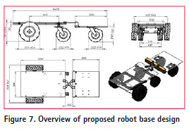
Hardware and software implementationThis section presents the structure of a mobile field robot, including a robotic base and an embedded circuit board design. Robotic base The design of a mobile field robot must take into consideration its environment, the weight it carries and the size of the mobile robot. We utilized the speed difference between the two front wheels for steering control of the robot. The coupling mechanism design increases both the carrying capacity and the scalability. The robot, including its two motors and four wheels, weighs approximately 17.2 kg. With the addition of an embedded board, spraying module, battery and tow tractor, the total weight increases to 29.2 kg. The overview of the proposed mobile field robot is shown in Figure 7.
Sensors The key components of the mobile robot were: the platform on which all modules are mounted; the multiple micro-controllers; the power circuitry; the motor controller; and finally, the sensors, including GPS module, Hall-rotary wheel encoders, an inertial measurement unit (accelerometer and gyroscope), an electronic compass, temperature/humidity (T/H) sensors, a laser range finder and a color sensor. GPS module The GPS module was produced by Parallax Inc. using an internal chip from the SiRF III chipset. The chip features 20 parallel satellite tracking channels for fast acquisition of National Marine Electronic Association (NMEA) data for vehicle navigation, telemetry or experimentation. The GPS module can interface with a microcontroller or even a personal computer (PC) via USB. Odometry Optical encoders are capable of calculating the distance a vehicle has traveled and provide information related to the direction of the vehicle. In this paper, optical encoders were used for secondary measurement of the vehicle’s heading and distance traveled. This data was used to supplement the information from the accelerometer and the gyroscope. Note that the sensors combined with IMU circuitry are capable of yielding far more accurate results and provide a more accurate estimation of the location of vehicles. Electronic compass This module employs a simple highprecision electronic compass capable of acquiring angles relative to North, according to the intensity of the magnetic field using BASIC programming language. In addition, it can make corrections anytime and internally set the desired bias angle to ensure that the vehicle maintains a fixed direction. The angle of direction is measurement in degrees functioning to determine the direction of a target and support the GPS module and IMU to accurately estimate the direction. Accelerometer and gyroscope Determining the relative location of autonomous vehicles is also necessary. The use of encoders to count wheel rotations is a good way to calculate distance and direction to determine the current position. Nevertheless, this method is susceptible to several sources of error including wheel slip. If wheels slip on the surface, the extra rotations result in inaccurate measurements of distance and direction. This paper used an accelerometer and gyroscope to determine the direction of the vehicle and support the GPS module to provide more accurate information. Semiconductor MMA7455L 3-axis digital output accelerometer is a low powered, micro-designed sensor capable of measuring acceleration along its X, Y, and Z axes. The module has a builtin ADC, low-pass filter, and selectable sensitivity range of ±2g, ±4g, or ±8g, which is perfectly suited to the proposed vehicle. LISY 300AL is a single-axis highprecision gyroscope, capable of providing a maximum detection rate of 300 degrees/ sec, maximum speed of 88 Hz and MEMs design of minimum size. Internally, the gyroscope sensor generates approximately 1.6 V on its analog when it is motionless. The output of LISY300AL was fed into a 10-bit analog to digital converter (ADC), with a high-speed (4 MHz) serial peripheral interface (SPI) and the signal pins capable of operating at 3.3 V and 5 V.
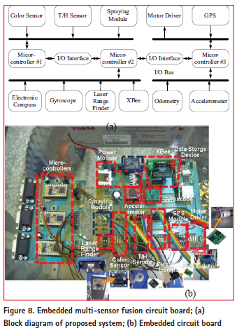
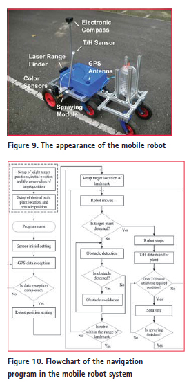
Laser range finder The laser range finder is produced by Parallax company. The sensor module uses propeller 8-bit core chip and CMOS camera to detect the range, which is between the laser center to the object. The maximum measure range of laser range finder is 2.4 meters. Color sensor The color sensor employed in this paper was the TCS230 module produced by Parallax. The module integrates many electronic components, including a TAOS TCS 230 RGB sensor chip, a lens, and two currentregulated white light emitting diodes (LEDs). Those sensors are capable of measuring all visible colors and performing the task of color identification through BASIC Stamp. Embedded circuit board design Figure 8(a) illustrates a block diagram of the mobile robot system, comprising three microcontrollers, MEMs and spraying module. The first controller (micro-controller #1) receives digital data from the color sensor, T/H sensor, and spraying command. The second controller (micro-controller #2) receives signals from the gyroscope, electronic compass, laser range finder, and 2.4GHz XBee module (IEEE 802.15.4 protocol). The third controller (microcontroller #3) receives the GPS navigation data, accelerometer data and odometer data. Figure 8(b) shows the appearance of the embedded circuit board. The GPS module is produced by Parallax Inc., using an internal chip from the SiRF III chipset. This module can interface with a microcontroller or even a personal computer (PC) via a Universal Serial Bus (USB) port. The IMU comprises an accelerometer, a gyroscope and an electronic compass, to collect data related to orientation and positioning. The laser range finder is used to detect the distance between obstacles and the mobile robot, to avoid collisions and maintain a fixed distance. A color recognition sensor is used for spraying. Data collected by each of the sensors is sent to the microcontrollers, where preliminary data processing is conducted. Data is stored with a heading identifier (ID) to identify the type of data. Thus, in writing the navigation algorithm, the micro-controller core was tasked with calculating the current location, based on the data collected from each sensor, and then conducting a dead-reckoning algorithm relative to the location of the target. A simple command setup enabled the motor control board to change the speed of the direct-current (DC) motor at any time and receive data related to the current status of the motor, such as speed or direction data. The control board could handle a maximum current output of 30 A and a maximum input voltage of 35 V, with the provision of an internal 10 KHz pulse width modulation (PWM) current control, which was very convenient for the implementation of motor-speed control. The proposed technique was implemented in an embedded system, which consisted of three micro-controllers (see Figure 8(b)). The programs of ‘color identification,’ ‘T/H detection’ and ‘spraying’ were written into the first micro-controller. The programs for ‘target tracking,’ ‘obstacle avoidance,’ and ‘decision mode’ were written in the second micro-controller. The programs for ‘motor controller’ and ‘dead reckoning’ in the navigation system were written into the third controller. The initial navigation parameters of the robot (including GPS data, landmark map, initial position of robot, obstacle position, relay position, etc.) and the fuzzy rule table were written to expand the memory module. Before the experimental testing, each sensor module had to be tested to determine whether it could operate properly a priori in its integration with the mobile robot system. After the evaluation of the individual components was completed, the fusion-system testing began. Experiment results and discussionIn many ways, farms are well-suited to autonomous guidance systems. For instance, the workspace does not change; landmarks may easily be installed in the corners of a field, which is then regarded as a stationary space. Crops usually include the same plants in the same places, which can be easily identified. In addition, with regard to such simple tasks as spraying and plant detection (identification), information given through the surrounding environment suffices to meet the same positioning demands. Even though the disadvantages of using mobile robot in greenhouses outweigh the advantages, adequate strides in related fields have been taken to justify proceeding with development. Therefore, the content of this section describes the testing process and evaluates the system performance of the mobile field robot, as shown in Figure 9. The electronic compass was mounted on top of the mobile robot to avoid electromagnetic interference. The T/H detection device was installed at the top of the water pipe. The servo motor module drives the pipe down, so that the T/H detection device could detect the value of T/H around the plant. The laser rangefinder was installed in front of the mobile robot and could perform horizontal rotation (about 180 degrees) through the servo motor module. Meanwhile, the laser rangefinder could be used for avoiding obstacles.
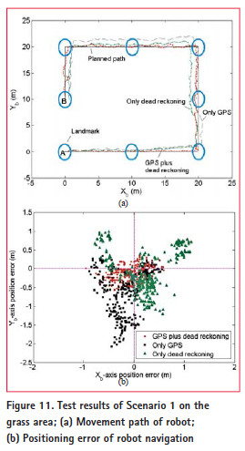
Testing was conducted in a constructed open area in Pingtung County, Taiwan. There were seven GPS satellites observed in the sky. For movement in an open area, the robot moved around the rectangular lawn in front of an apartment building at the National Pingtung University of Science and Technology (NPUST), Taiwan. The selected test area was approximately 20 meters square. The circumference was 70 meters, with ‘A’ as the starting point and ‘B’ as the endpoint. In this experiment, the locations of eight points were measured and recorded in advance within the robot’s system. A path was then planned with these points known beforehand. The robot moved clockwise based on the planned path, with each corner set at 90 degree angles. It was necessary to set a range to determine whether the robot reached the landmark, and the radius was set at 1.25 m. As long as the robot was within range of the landmark, it was considered to have reached the target landmark and could move toward the next. Two experimental scenarios were developed and demonstrated. In the first scenario, the functionality of autonomous navigation of the mobile robot was tested. The second scenario involved the mobile robot navigating in the presence of obstacles and plants. The user could set the desired path, the locations of obstacles and plants and the color value. A flow chart of the program is shown in Figure 10. The data (desired color range, planned path and location of landmarks) needed to be recorded before starting the mobile robot. Once the robot detected the desired color values, the T/H sensor module was then used to detect the temperature and humidity values around the plant. If the T/H value was below the desired value, the spraying operation was performed using that module. In addition, the laser range finder was employed to detect obstacles in front of the robot. After the process of color-detection and obstacle-avoidance, the mobile robot moved toward the nearest landmark. If it moved into the range of the landmark, the next landmark became the desired location. Scenario 1: Autonomous navigation test The purpose of this experiment was to test the ability of the mobile robot to follow a path, using its IMU component or its electronic-compass module in conjunction with the GPS module and the odometer, through a proposed scheme. In the setup of the experimental parameters, it is necessary to calibrate the gyroscope and accelerometer before its use. This could be done at startup by making sure the gyroscope and accelerometer are stationary, whose output values (500 data) are sampled using the analog-todigital converter (ADC) to obtain the root mean square value. This value could be acquired each time at startup, or it could be stored after initial calibration. The variance of and are 0.23 m/s2 and 0.26 m/s2, respectively.
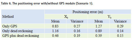
The sampling time of the GPS module was setup as 1 Hz. The output of the data rate of the accelerometer and the bandwidth of the gyroscope were 125 Hz and 88 Hz, respectively. This would be fine for a typical mobile robot navigation. After the adjustment of the parameters, the GPS module performed a ‘warm start,’ and then the navigation program started to calculate the position of the mobile robot. As the mobile robot reached the set range of landmarks through its navigation system, it began to search for the next landmark. Figure 11(a) demonstrates the experimental results under different combination method on the grass area. From Figure 11(b), it can be seen that the average position errors of direction and direction with GPS plus dead reckoning method are 0.46 m and 0.39 m, respectively, which produces high accuracy in positioning. The average positioning error with and without (w/o) GPS is demonstrated in Table 6. By referencing the estimated position and the desired positioning data, the position error could be calculated. From Table 6, it can be seen that the adoption of the GPS plus dead reckoning method with the multi-layer fuzzy control system resulted in the lowest degree of positioning error.
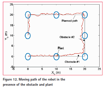
Scenario 2: Obstacle avoidance and plant-spraying tests The second scenario was conducted in a field in which the robot was required to spray and identify a colored object when it moved. When objects were detected, the robot stopped and sprayed them, using a sprayer. While moving, the robot followed a planned path. Colored objects were placed near the planned path to test the detection performance of the robot. The functions of obstacle avoidance and plant spraying were tested in the outdoor environment. The information regarding the locations of obstacles and plants were recorded in the memory module of the mobile robot beforehand. After 10 testing, the average path of motion for the robot was as demonstrated in Figure 12 (The blue dot represents an obstacle; the pink dot represents the plant.). As is shown, the robot stopped where it encountered the colored objects and sprayed them. In addition, the mobile robot avoided the obstacle successfully. However, the robot could not reach into the range of landmarks successfully. ConclusionsThis paper proposes a low-cost microcontroller, in conjunction with an MEMs component, to produce a multisensor embedded navigation system for implementation in a small mobile field robot. A multi-layer fuzzy system was utilized in robot navigation, spraying and obstacle avoidance. The use of the proposed decision scheme could enhance the positioning accuracy in both and directions, to 0.46 m and 0.19 m with 0.2 m/s, respectively, over uneven pavement and with known landmarks. In addition, the positioning accuracy effect of the mobile robot in the presence of different sensor combinations was analyzed. Although the adopted IMU sensor resulted in accumulated positioning errors, the precision of positioning was significantly improved by adjusting the scale factor and bias using software and odometry. The navigation system was equipped with GPS/IMU/ odometry sensors, which could cause the positioning errors in both the and directions to reach 0.76 and 1.43 meters, respectively, at a speed of 0.2 m/s. Overall, this system was flexible in combining different sensor elements for navigation, and also allowed for installation of the different brand sensors to an embedded board. The proposed mobile field robot succeeded in detecting and accurately identifying objects, as well as spraying, during experiments in a field. The total cost of the robot was approximately US$ 930, including design, implementation and system integration, which was inexpensive considering the quality of the components used. This study implemented the concept of a multisensor embedded system in a mobile gardening robot, which may be valuable for future applications in greenhouses. AcknowledgementsThis work has been supported by the National Science Council, Taiwan, Republic of China, under grant NSC 101-2221-E-020-018. |


 (14 votes, average: 4.50 out of 5)
Exciting results.
It is a good method with importment information.
Leave your response!
MY NEWS
Stonex launches hybrid mobile mapping solution Leica Geosystems launches TerrainMapper-3 Enhancing U.S. Navy’s MQ-25A UAS YellowScan Navigator Bathymetric LiDAR system SECO launches Qualcomm-based SOM-SMARC modules
More...________________________________________
The Drone Rules in India 2021
________________________________________
National Geospatial Policy of India 2022
________________________________________
Indian Satellite Navigation Policy – 2021 (Draft)
________________________________________
Guidelines for acquiring and producing Geospatial Data and Geospatial Data Services including Maps
________________________________________
Draft Space Based Remote Sensing Policy of India – 2020
________________________________________
National Unmanned Aircraft System (UAS) Traffic Management Policy – Draft
________________________________________
Advertisement
Interview
Air Vice-Marshal Kym Osley
CSC, FAIN, Executive Secretary, Australian Institute of Navigation (AIN)
Easy Subscribe
NSDI in India
PREVIEW THE BOOK
Previous Issues
- Vol. XIX, Issue 12, December 2023
- Vol. XIX, Issue 11, November 2023
- Vol. XIX, Issue 10, October 2023
- Vol. XIX, Issue 9, September 2023
- Vol. XIX, Issue 8, August 2023
- Vol. XIX, Issue 7, July 2023
- Vol. XIX, Issue 6, June 2023
- Vol. XIX, Issue 5, May 2023
- Vol. XIX, Issue 4, April 2023
- Vol. XIX, Issue 3, March 2023
- Vol. XIX, Issue 2, February 2023
- Vol. XIX, Issue 1, January 2023
- Vol. XVII, Issue 12, December 2022
View AllLog In
E-ZINE
- December 2023
- November 2023
- October 2023
- September 2023
- August 2023
- July 2023
- June 2023
- May 2023
- April 2023
- March 2023
View AllPartnership
February 13-15, 2023
Denver, USA
27 Feb to 01 March
London, United Kingdom
15-16 March 2023
Singapore
15-16 March 2023
Singapore
23 March 2023
17-18 May
London, UK
14-19 May 2023
Baska, Croatia
22 - 25 May 2023
Kuala Lumpur, Malaysia
5-7, September 2023
Las Vegas, USA
11-15 September
Denver, Colorado, USA
10-12 October
Berlin, Germany
November 1-2, 2023
Maryland, USA
6-8 November
Calgary, Canada
8 - 10 November
Gyeonggi Province
Republic of Korea.
11-13, February
Denver, The USA
14 - 15 February 2024
Dubai, UAE
6-7 March, 2024
Singapore
11-13 March
London, U.K.
29 - 30 April
Kuala Lumpur, Malaysia
2-4 May 2024
Angers, France
14-15 May 2024
Ottawa, Canada
05 - 06 June
London, UK
View Past Events