| Mapping | |
Land parcel 3D mapping using terrestrial laser scanning
This article is about the 3D mapping areas of parcel by the method of Terrestrial Laser Scanning (TLS) for the purposes of coastal management that is required by the Government of DKI Jakarta |
 |
|
 |
|
 |
|
Laser scanning is one of the latest techniques applied in 3D survey and mapping. Currently it is the leading survey technology providing spatial data information. Laser scanning is a process of recording precise 3D information of real world objects or environments. There are many types of measuring instruments that use laser scanning technology with a range of capabilities for a variety of applications (Staiger, R., 2003). Heinz Stanek (2004), stated that applications of lasers scanners are successful in wide areas of documentation of surfaces and objects. Almost, the general principle of data acquisition must be optimized in specific ways. For the data acquisition the demanded precision and density, but also the number and distribution of reference points may vary.
According to Jagannath Hiremagalur et.al (2009), TLS measure thousands of data points (distance, angle, and reflected return signal power) per second and generate a very detailed “point cloud” data set. Using TLS will dramatically improve safety and efficiency over conventional survey methods. However, to fully realize the benefit of using TLS, they must be used properly and in appropriate applications. Mike Pinkerton, (2010) stated that how Terrestrial Laser Scanning solutions have been applied on projects where up until very recently traditional surveying methods would have been the norm. As more people are made aware of the benefits of laser scanning, then their expectations from their spatial data suppliers will rise accordingly. Concurrent with this change in attitude will be ongoing further refinement of technology (both hardware and software). The end result will be that laser scanning technology, like real time GPS did before it, will inevitably become commonplace within the realm of mainstream land surveying. According to R H Alkan and G Karsidag (2012), data obtained from laser scanner has a high quality and widely used in various fields, particularly those surveys that include topographic surveys, environmental and industrial.
The main advantage of mapping surveys using laser scanning technology, can provide complete facilities to perform data acquisition and can give detailed data in 3D, as well as the results can be obtained quickly dam costs could be reduced significantly. Laser scanning technology is one of the latest techniques in 3D mapping and survey technology is the latest survey to obtain information on the spatial data. There have been many kinds of measuring instrument that uses laser scanning technology with a range of capabilities. In the field of survey mapping, laser scanning equipment is a new dimension in spatial data collection (Sadikin Hendriatiningsih et.al, 2014). This article is about the 3D mapping areas of parcel by the method of Terrestrial Laser Scanning (TLS) for the purposes of coastal management that is required by the Government of DKI Jakarta. In this study, the building height is measured from georeferenced 3D models.
Methods and results
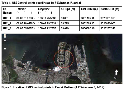
The equipment used is TLS Optech ILRIS Model 36D, the prism used as targets, computer, software Polywork, Geomagic Studio 2013, AutoCAD, Google SketchUp, and accessory equipment for completeness. Location GPS control points in the area of Pantai Mutiara, as in Figure 1, as follows:
The control points are in zone 48 S in the UTM projection system, and the coordinate data points that the GPS control point NRP_1, NRP_2, and NRP_3 are shown in Table 1.
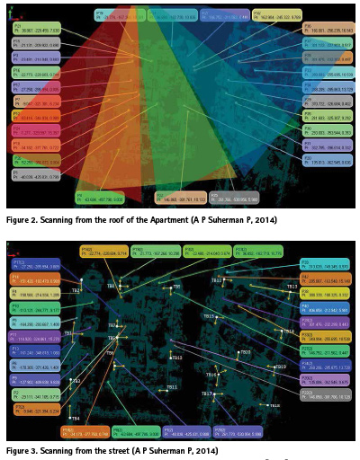
The next is to plan the placement of TLS instrument for scanning. Field of view of the equipment TLS is 40 ° x 40 °, then scanning the object consists of four sections in one place standing instrument TLS with overlap of 4 °. Scanning from the roof of the apartment as shown in Figure 2.
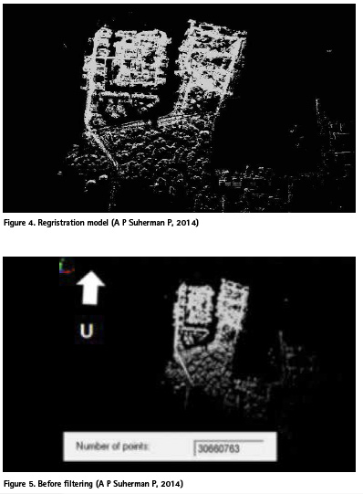
To complete the area being scanned from the roof of the apartment, the next scan is done on the road (from the street) to complete the data scanning. Scanning from the street to the prism point location, as shown in Figure 3.
TB = TLS location
P = Prism point location
Data processing point clouds to get a 3D solid model is doing some stage, namely registration, filtering, georeferencing, and modeling.
The registration process carried out by separating the registration based on the location decision, namely the registration scanning from the roof of Apartment and from the street. Then the two registrations are combined to form complete object. The registration model can be seen in Figure 4.
And the average registration error is 0.0191 m.
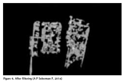
Filtering is delete for unnecessary data. This is done by manual, by identifying the objects that are not necessary, then the objects been removed. Before filtering, as shown in Figure.5. And after filtering, shown in as Figure 6.
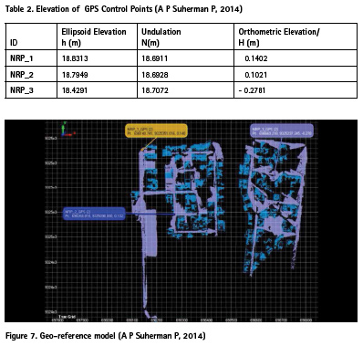
Next, calculate the undulation and orthometric elevation of GPS control points, and the results are as shown in Table 2.
In the GPS control points, placed prism and scanning, which prism P14 installed at the control point (NRP_1), the prism P1 at the control point (NRP_2) and the prism P29 at the control point (NRP_3), in order to obtain geo-referenced models, such as shown in the Figure 7.
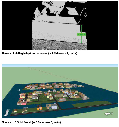
Building height is measured from the model geo-referenced as the Figure 8.
Furthermore, the modeling is done using software Geomagic, AutoCAD, and Google Sketch Up, 3D solid model is obtained as shown in the Figure 9.
Conclusion
– Mapping 3D parcels can be done with a laser technology equipment as TLS and building height is measured from the model geo-referenced
– In 3D cadastre, requiring detailed shape of the building, so it should be no permission for the scanning from the owners of the parcels.
– The 3D solid model, can support the management of coastal areas of Government of DKI Jakarta.
References
[1] A P Suherman P, 2014, Survei Pemetaan Menggunakan Alat Berteknologi Laser Scanning Untuk Mendukung Informasi Spasial 3D, Seminar TA, Program Studi Teknik Geodesi dan Geomatika, FITB – ITB, 28 Februari 2014.
[2] Heinz Stanek, 2004, Terrestrial Laser Scanning: Universal Method or a Specialist’s Tool?, INGEO 2004 and FIG Regional Central and Eastern European Conference on Engineering Surveying Bratislava, Slovakia, November 11-13, 2004
[3] Jagannath Hiremagalur, Kin S. Yen, Ty A. Lasky, Bahram Ravani, 2009, Testing and Performance Evaluation of Fixed Terrestrial 3D Laser Scanning Systems for Highway Applications, Transportation Research Board 88th Annual Meeting 2009, Advanced Highway Maintenance and Construction Technology (AHMCT) Research Center Department of Mechanical & Aeronautical Engineering University of California – Davis, Paper no 09-1995, 2009
[4] Mike Pinkerton, 2010, Terrestrial Laser Scanning for Mainstream Land Surveying , Proceeding FIG Congress 2010, Sydney Australian, 11-16 April 2010
[5] R H Alkan and G Karsidag , 2012, Analysis of The Accuracy of Terrestrial Laser Scanning Measurements, FIG Working Week 2012 – Commission: 6 and 5 – Knowing to manage the territory, protect the environment, evaluate the cultural heritage Rome, Italy, 6-10 May 2012, Editors: Prof. Rudolf Staiger & Prof. Volker Schwieger, TS07A – Laser Scanners I, 6097, 2012 (Conference Proceedings ISBN 97887-90907-98-3).
[6] Sadikin Hendriatiningsih, Irwan Gumilar, Dwi Wisayantono, Elok Lestari P, 2014, ”Survey Pemetaan Model Bangunan 3D metode Terrestrial Laser Scanner untuk Dokumentasi As-Built Drawing”. Jurnal Teknik Sipil, Vol 21, No.2, Hal 95-178, Bandung, Agustus 2014, Jurnal Teoritis dan Terapan Bidang Rekayasa Sipil, FTSL – ITB, ISSN: 0853-2982,
[7] Staiger, R., 2003, Terrestrial Laser Scanning-Technology, System and Application, Proceedings of 2nd FIG Regional Conference, ISBN 87- 90907-28-0, Marrakech, Morocco, December 2-5, 2003, Editors: Taïb Tachalait & J. Schnurr, TS 12.3-Positioning and Measurement Technologies and Practices, 2003. The paper was presented at FIG Working Week 2017, Helsinki, Finland, May 29, June 2017.


 (1 votes, average: 1.00 out of 5)


Leave your response!