| Surveying | |
The Jamaica VRS and Cadastral Surveying
Field testsAs part of our research activities at the University of Technology, Jamaica, various field tests on the system were carried out, so as to provide enough information to analyse whether the geodetic control can be an adequate integrity monitor and how well the VRS is adaptable to cadastral surveying.
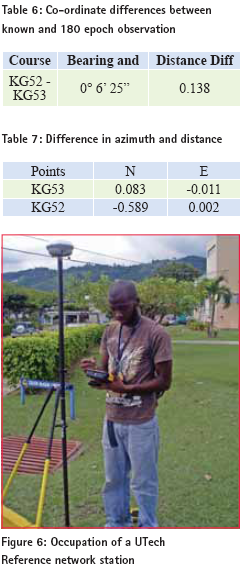
Seven (7) of the nine (9) points which constitute the National GNSS Calibration Network were occupied using an active VRS receiver. This network of points will form the basis of legal traceability for Cadastral Surveys in Jamaica. The tables 4 and 5 below set out the results. The results obtained from the National GNSS Calibration Network observation provided satisfactory results and were of high quality as the differences in horizontal distances ranged from 0 millimetres over a distance of 41.073 to 11 millimetres over a distance of 196.242 meters. The proportional accuracy (1/17,840) is low, due to the line being very short. The differences in the orientation were minimal and ranged from 1 second of arc (1”) to 11 seconds (11”). The differences in the co-ordinates displayed consistency around the 5cm level in the northings for all points when compared with the known coordinates obtained from the Survey and Mapping Division of the National Land Agency (SMD_NLA), Jamaica. However the eastings differences fared better at the 2 cm level. Kingston’s Densifi cation Network Stations Two (2) points which are part of the densification of the national control network in the City of Kingston, were occupied. The tables 6 and 7 below show the results. The Point KG53 exhibited differences of less that 10cm. However KG52 exhibited 0.589m in northing which suggest the presence of a source of significant error in the determination of these coordinates. This could have been the result of multipath due to the passing traffic, as both stations are sited in sidewalks. KG53 was also partially covered by the foliage of a nearby tree. Data logging was still possible as the receiver maintained lock and carried out recorded data. However, warnings of poor satellite geometry were being received through the TCS2 Controller. This case underscores the need for a clear and unobstructed “view” of the sky for the location of GNSS control stations if optimum GNSS results are to be realised. It should be noted however that these points were established by Total Station Traversing and not for use with GNSS.
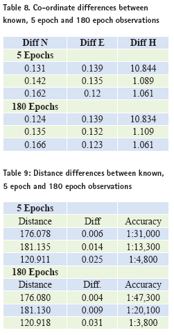
Three (3) of the twenty-eight (28) control stations on the campus of the University of Technology (UTech), which forms a reference network that allow student to geo-reference their surveys and provide a means of checking the accuracy of their work, were observed using an active VRS receiver in order to evaluate the accuracy of the VRS in this type of environment characterized by a high density of concrete canopy. Distances were computed in order to compare the known distances with their observed values. Control Stations UT09, UT25A and UT27 were those used. There was a negligible difference between the 5 epoch observation and 180 epoch observation. The differences between the known and measured VRS co-ordinates were in the range of -0.166 m in Northings and 0.139 m in Eastings. UT09 exhitbited a 10m bias in elevation. This indicates a blunder in conversion of the GNSS ellipsoidal height to Geoidal height. The height differences exhibited by the other stations are expected, as the geoidal model (CARIB97) that is currently in use, is not dense enough to provide good quality mean sea level elevations across the island. Differences of up to 2.5m have been reported by GNSS users on the island. There is a need for a more accurate local geoid model. The distances differed by between 3.7 mm and 31.1 millimeters, with resulting proportional accuracies of between 1/3,800 and 1/47,300. This site is well populated with buildings and trees that would have had a negative impact on the quality of these results.
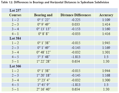
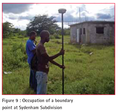
In carrying out observations on a parcel in an Urban part of the parish of Saint Andrew, only seven (7) of the fourteen (14) boundary marks that were present on the site were occupied using the VRS. This was due to the many sources of obstruction, including boundary walls (see figures 7 and 8), and a building on the parcel. The receiver frequently lost lock from the Satellites’ signals. Poor satellite geometry warnings were also frequent from the TCS2 controller, this contributed to poor results obtained for the VRS survey. Although the two lines for which reasonable comparisons could be made appears acceptable (in distances), the fact that only two boundary lines delivered satisfactory results, suggests that this survey represents those in which it is best to use the VRS to geo-reference the survey (soon to be mandatory) by establishing control points, in the best GNNS friendly locations on the site, and use conventional means of surveying to complete the survey. As a part of the regulatory requirements for this type of survey, a tie had to be made to the nearest street intersection. This required three (3) traverse stations and about 45 minutes, using the total station. A 300 second VRS occupation of the tie point yielded a difference of 12 mm over the distance of 121.5 m, thereby realising an accuracy of 1/10,123.This is encouraging for the proposed mandatory geo-referencing of cadastral surveys across the island, although our mostly erratic landscape will pose some challenge to even this minimal application, in some areas. Subdivision VRS observations that were carried out in the Subdivision of Sydenham Villas, Saint Catherine were challenged by the unavailability of marks as the area is swampy and, according to the residents heavy machinery was used to clear the parcels of vegetation. During the clearing of the land, pegs were either disturbed or knocked out. The intention was to acquire information for a block of parcels in the subdivision. This was not possible due to the aforementioned circumstances. However, after searching, a few boundary marks were located. Using the VRS receiver to occupy the marks was trouble-free as all locations had a clear view of the sky.
SummaryThe results obtained from the Virtual Reference System (VRS) surveys of the test sites, in some instances, are unfavourable. The differences in Northings and Eastings on the Calibration Network points range from 14 mm to 60 mm. Much better results would be expected, as points are located in an ideal GNSS friendly site. There appears to be a systematic bias between this network and the VRS Network.. The horizontal distance observations differences ranges from 0 mm to 11 mm. Considering that these observations were done in perfect “view” of the sky and conditions were very favourable for GNSS observations, one would have liked to see much better results. It could be that occupation times needed to be longer, depending on the number of satellites available at the time of the survey. If such good conditions are available on cadastral surveying sites, then the system would be very suitable for geo-referencing surveys. The test observation which was done on the Urban area control points, returned disappointing results. This because the station KG52 was covered with foliage, even though this did not stop the receiver from logging data. The TCS2 controller warned the user with a clear sound ‘poor satellite geometry’. The TCS2 controller and the VRS software does not collect data unless Root Mean Squared Error (RMSE) quality indicator falls within the limits entered during the setup stage. The -0.589m difference in Northings may be also as a consequence of other factors including multipath, due to the presence of a building with many glass windows less than 50 meters away from the station. The distance difference of 13.8 centimeters is poor obviously due to unacceptable GNSS site conditions. The rural survey which is located in the Kitson Town area of Saint Catherine, served up results that are less than acceptable for cadastral surveying standards (Rural – 1/500) in Jamaica. There are significant inconsistencies where the courses are concerned. An acceptable distance measurement was achieved for only one line for which the accuracy a little better than 1:500.The active receiver had problems initializing in this area after initializing the observations were carried out in quick succession of each other. Warnings were, however, received of ‘poor satellite geometry and poor observation’. The observations were however still carried out and logged by the instrument. The observations could have been subject to cycle slip which would be caused by the tree canopies in the area. The subdivision survey which was carried out in the Sydenam area of Saint Catherine, where the acceptable standard of accuracy is expected to be atleast 1/1,000, was also subjected to similar sources of errors to those experienced in the Kitson Town. Although the site was not as dense, there was some difficulty initializing the instrumentation and loss of base station information was frequent. This is due to the fact that voice is given priority over data in the cellular network. If communication channels are occupied by streaming data for the VRS and a cellular phone user dials to make a call, the data streaming will be discontinued if the channel being used to transmit data is the only channel that can effect that call. This situation proves to be very disruptive and can detract from the use of VRS. In the case of the control points on the UTech campus, there appears to be a systematic bias in the Northings and Eastings of the points, which may be explained by a weakness in the tie of this network to the National Grid. The same can be said for the elevation differences, except of course for point UT09, which appears to be the result of a blunder. The distance differences demonstrate that there is good potential for VRS in this type of environment. The cadastral observations at the selected urban site, in terms of quality, were poor. In this type of survey our regulations require that the minimum standard of accuracy is 1/2,000. The points were located in proximity to high wall/fences and other structures which blocked satellite signals and caused poor satellite geometry, resulting in poor observations. Some points could not be directly observed as they were covered by structures, others did not allow for a vertical receiver pole because of close structures. Only seven (7) of the fourteen (14) points could be occupied and even these did not yield acceptable results. ConclusionThe main objective of the research was to determine if the VRS can be used satisfactorily to carry out cadastral surveying in urban, rural and subdivision sites and whether or not our geodetic infrastructure can serve as a good integrity monitor. Satisfactory results in cadastral surveying can be achieved where sites exhibit GNNS friendly conditions. The results from the National Calibration Network, which is to be used for the legal traceability of GNSS measurements in Cadastral Surveys, are encouraging, but also enforce the point that excellent site conditions are mandatory. The results of the test on the University of Technology control network strongly support this argument. The use of the instrumentation is very practical and simple and with a clear “view” of the sky the system can deliver high accuracies. It allows for more expedient observations in comparison to Total Station surveys. If used in the right conditions i.e. where there is clear unobstructed “view” of the sky, which may be the case in only about 30% of Cadastral Surveys in Jamaica, it can be open to many other practical surveying applications, such as Geodetic, Engineering and Topographical surveying. The Virtual Reference System (VRS) method can be a suitable alternative method of carrying out Cadastral Surveys in Jamaica, provided that there is clear “view” of sky at all boundary points and the pole is able to be held vertically, while on the boundary mark. However, when there are obstructions a combination of conventional instruments and GNSS method can be used to good effect, which involves both the Total Station and the Virtual Reference System (VRS). The results have demonstrated that the 10cm and 50cm accuracies required in geo-referencing Urban and Rural Surveys respectively, can be achieved, where conditions allow. Likewise, where national control is located in GNSS friendly locations, they may be used as integrity monitors for the VRS, prior to and after a survey is done, to provide the user with a high level of confidence in the system, that it is providing good results. It is the density of such points that would remain a concern. RecommendationThe Total Station and VRS approach is therefore recommended whenever such difficulties arise such as in the case of the survey of an urban lot. Monuments which are located in areas with a clear view of the sky can be occupied with an active VRS receiver. Control stations can be set using the VRS and points which cannot be observed using the single active receiver can be surveyed using a total station. ReferencesStandards & Guidelines for Cadastral Surveys Using Global Navigation Satellite Systems. (2006, July 26). Retrieved May 9, 2010, from U.S. DEPARTMENT OF THE INTERIOR BUREAU OF LAND MANAGEMENT: http://www.blm.gov/ A. Pirti, N. A. (2009). Real-Time Kinematic GPS for Cadastral Surveying. Survey Review, 339-351. Al Marzooqi, Y., Fashir, H., & Babiker, T. (n.d.). Establishment & Testing of Dubai Virtual Reference System (DVRS) National GPS-RTK Network. Retrieved May 20, 2010, from GIS Development (The Geo Spatial Portal): http://www.gisdevelopment. net/technology/gps/me05_131.htm Andrews Space & Technology. (2001). GLONASS Summary. Retrieved May 10, 2010, from Space & Tech: http:// www.spaceandtech.com/spacedata/ constellations/glonass_consum.shtml Collier P.A. and Bowen N.J. (1999) A GDA94 Transformation Grid for Tasmania. The Australian Surveyor. Vol. 44, No. 2 El-Rabbany, A. (2002). Introduction to GPS: The Global Positioning System. Boston: Artech House. Encyclopedia of the Nations. (2010). Jamaica – Location, Size, and Extent. Retrieved May 12, 2010, from Encyclopedia of the Nations: http://www. nationsencyclopedia.com/Americas/Jamaica- LOCATION-SIZE-AND-EXTENT.html Estopinal, S. V. (2009). A Guide to Understanding Land Surveys. New Jersy: John wiley & Sons Limited. French, T. G. (1996). Undestanding The GPS: An Introduction to the Global Positioning System. Bethesda: GeoResearch Inc. Girvan, R.A., (1983) Report on Jamaica MSL Datum with respect to new data received from the U.S. National Ocean Service Survey Department Internal Report Jamaica Girvan, R.A., (1983) Admiralty Datum Survey Department Internal Report Jamaica Girvan, R.A., (1984) Jamaica Horizontal Adjustment (JAD69) Survey Department Internal Report Jamaica Gleason, S., & Gebre-Egziabher, D. (2009). GNSS Applications and Methods. Boston: Artech House. Grewal, M. S., & Weill, L. W. (2001). Global Positioning Systems, Inertial Navigation, and Integration. New York: Jon Wiley & Sons Limited. Hakli, P. (2004). Practical Test on accuracy and Usuability of Virtual Reference Station Method in Finland. Positioning and Measurement Technologies and Practices I – GNSS Networks (pp. 1-16). Athens, Greece: FIG Working Week. Hofmann-Wellenhof, B., Lichtenegger, H., & Collins, J. (2001). Global Positioning Systems: Theory and practice. New York: Springer Wein. Jeong, J.-Y. (2010, April 11-16). Use of Network RTK using VRS for a Cadastral Surveying on Islands. Technology in Land Administration. Sydney, Australia: FIG Congress. McCarthy, D. D., & Seidelmann, K. E. (2009). Time: From Earth rotation to Atomic Physics. London: Wiley VCH. Mugnier C. (2003). Grids and Datums. JAMAICA. Photogrammetric Engineering & Remote Sensing May 2003 National Research Council. (1995). The Global Positioning System: A Shared National Assest. Washinton DC: National Academy Press. Newsome, G. G. (2001). Towards a Virtual reference System (VRS) for Jamaica. Retscher, G. (2002). Accuracy Performance of Virtual Reference Station Networks. Journal of Global Positioning Systems, 40-47. Roberts, C. (2005). GPS for Cadastral Surveying – Practical Considerations. SSC 2005 Spatial Intelligence, Innovation and Praxis: The National Be\iennial Conference of the Spatial Sciences Institute. Australia: Spatial Sciences Institute. Robinson, R., (1975). A critical review of the mapping of Jamaica from 1938 to 1973. Unpublished R.I.C.S. Final Examination Dissertation Scott, L., & Beidleman, W. (2006). GPS Versus Galileo (Balancing for Position in Space). Alabama: Air University Press. Silayo, E. H. (2005, April 16- 21). Searching for an Affordable and Acceptable Cadastral Survey Method. Retrieved May 9, 2010, from International Federation of Surveyors: http://www.fig.net/pub/cairo/abstracts/ ts_39/ts39_03_silayo_abs.pdf Tsui, B.-Y. J. (2000). Fundamentals of Global Positioning System Recievers: A Software Approach. New York: John Wiley & Sons Inc. U.S. Department of Homeland Security. (1996, September). NAVSTAR GPS User Equipment Introduction. Retrieved May 10, 2009, from Navigation Center: The Navigation Center of Excellence: http://www.navcen.uscg.gov/ pubs/gps/gpsuser/gpsuser.pdf US Army Corps of Engineers. (2003, July 1). NAVSTAR Global Positioning System Surveying. Engineer & Design. Washington DC, United States of America: Department of the Army.
|


 (7 votes, average: 3.86 out of 5)


Leave your response!