| Navigation | |
Solving the GPS gap
|
Antonio Angrisano, Armando Pacifico, Mario Vultaggio
|
||||
|
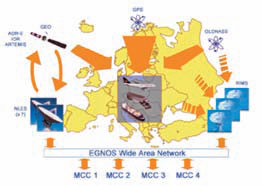
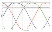
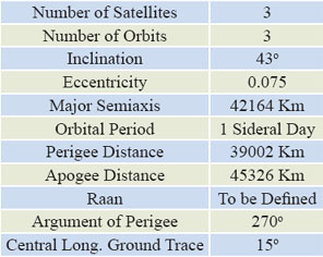
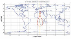
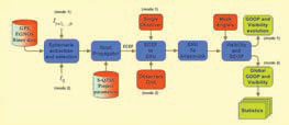
The current GPS civil service provides suitable performance only in situations of good electromagnetic visibility; the positioning becomes Detailed coverage analysis of a super-constellation made up of GPS+EGNOS+S-QZSS is presented, based on existent GPS-EGNOS satellites and hypothetical Shifted- QZSS constellation over Europe. Both systems, in different way, could improve the main parameters that quantify the performance of a navigation satellite system, i.e. availability, accuracy, continuity and integrity, but their own constellations have different features and different potential uses. Fig.1: EGNOS Architecture The used indicators, to compare the various satellites configurations, are the VSN (Visible Satellites Number) and GDOP (Geometric Dilution Of Precision), which represent the quality of positioning; suchparameters are computed for a single observer and global observers grid, particularly in Europe. A statistical analysis is also introduced in order to obtain meaningful results. Moreover we will define a Service Area. BackgroundEGNOS is the European SBAS (Satellite Based Augmentation systems), it has been developed by the ESA in co-operation with the European Commission and Eurocontrol. The system is made up of 3 segments (Fig.1): Space segment, Ground segment, User segment. In this paper we are focused on space segment, which is composed by already existing GPS constellation and 3 geostationary satellites broadcasting WAD (Wide Area Differential) corrections and integrity informations. Geostationary satellites also broadcast GPS-like signal that should improve the satellites geometry. EGNOS already works, but is under final phase of testing and will be declare operative (as system) during 2008. QZSS (Quasi Zenith Satellite System) is a joint program of the JAXA and a consortium of Japanese industries; QZSS is a space-based positioning system, designed to be a GPS augmentation on urban and QZSS is composed by a Space Segment, a Ground Segment and a user segment. The Space Segment consists of three geosynchronous satellites that move on three identical Higly-inclined Elliptical Orbits (HEO) with coincident 8-shaped ground tracks centred on 135°E meridian. QZSS constellation is planned to have always at least one satellite near zenith over Japan, so that users can receive signals without obstructions in “urban canyons” and mountainous areas. Fig.2: S-QZSS satellites heights and sky-plot (observer at Naples) In order to do such simulation we use a constellation obtained by ideally shifting the QZSS constellation on Europe, changing only central longitude of ground trace (15°E). We call the simulated constellation “Shifted-QZSS” or S-QZSS to distinguish it from the original one. The The constellation is conceived to have at least one S-QZSS satellite always visible at elevation angle more than 75° from service area; SV at elevation angles of 70°-80° is usually visible for observers placed in urban canyons. Fig.3: Shifted-QZSS orbital parameters Fig.4: S-QZSS ground tracks Coverage analysisWe want to examine the worldwide and European coverage, provided by GPS and EGNOS and S-QZSS augmentation. For this purpose we have developed a simulation software in MATLAB® environment, resumed in the block diagram in Fig.5. Inputs are GPS and EGNOS Rinex navigation files, which contain the daily broadcast ephemerides. Rinex data, related to 02/16/2008, were stored by a Septentrio PolaRx2 receiver placed near Naples. The algorithm first block deals with the extraction and selection of GPS/EGNOS satellites ephemerides from Rinex files. The selected ephemerides and the theoretic S-QZSS orbital parameters are the inputs of an orbit propagator, which updates the ephemerides at observation epoch. The satellites ECEF coordinates, outputs of orbital propagator, are transformed in the local ENU coordinates and then in elevation and azimuth relative to the observer. In the last block of the software, VSN and GDOP are computed for a given mask angle. The software can work in two ways: Fig.5: Software block diagram |
||||



 (No Ratings Yet)


