| Surveying | |
River cross-section surveying using RTK Technology
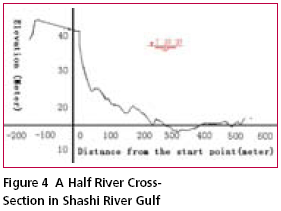
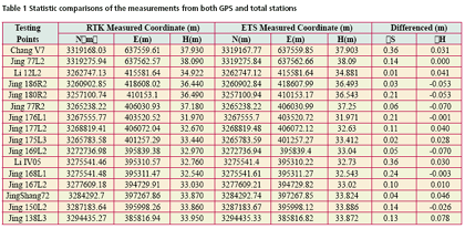
Cross-section survey of the riverCross-section survey of the river depends on cross-section measurement method used. The cross-section interval will be set about 200 meters apart, and Trimble 5700 GPS is used to fix horizontal position. GPS reference stations are located at open, ashore known points so that the reception of GPS satellite signals is not potentially blocked and the data link of GPS signal transmission does not pose any problem. GPS roving station is located in a powerboat for bathymetric survey. A common set of GPS satellites are recorded at both the reference and rover stations simultaneously. Coordinates of the mobile station are computed using both the received GPS satellite information and the differential information from the reference station via the data link. The SDH-13D digital echo depth sounder is used to measure water depth of the points. The sounding pole of the echo sounder and the GPS rover station antenna are put in the identical horizontal position. The echo sounder is controlled by the computer to collect water depth signals in an electronic form and then transformed into a digital form (i.e. numbers). The river cross-section survey data collection and recording is carried out by the laptop computer with the Hypack survey software. Each cross section line is roughly perpendicular to the shoreline with an interval of 200 meters. Before the survey is carried out, the space of the measurement points needs to be established in the Hypack survey software. The survey boat is driven along with the cross section line while the laptop computer collects coordinates and the depth of water automatically. The height is measured through trigonometrical leveling with ETS. The height of each cross section is derived from the ETS. The elevation of the underwater surveying point is therefore deduced from the water level and the water depth. During the survey process, water level at the related hydrometric station and water level observation station is recorded at the same time for a necessary check. Data processing and visualizationThe office work consists of the following two parts: data edition and visualization After the field survey work, GPS data which is recorded in the receiver/or data card needs to be downloaded through Trimble proprietary software package – TGO (v1.6). Four data files will be created. They are observation file (*.o) carrier phase and pseudo range observation file, navigation file (*.n), epoch parameter file and survey station information file. GPS baseline vector is processed in order to promptly check the quality of the field observation data. 17 control points of Shashi river reach are used as checking points to evaluate the RTK GPS results. Coordinates from GPS RTK are compared with the coordinates derived from Electronic Total Station measurements. The results are listed in the following Table 1. As for the height component, China national standard datum is used. The model of Electronic Total Station is Nikon DTM532 – C, with an angle measurement precision of 2 seconds and distance measurement precision of 2mm+2ppm. The maximum distance measurement range is 3,600 meters. According to the statistical results shown in Table 1, the maximum difference of the horizontal locations among the control points is 0.36m. The elevation difference is generally less than 0.1m, which illustrates the coordinates by RTK method and ETS is within the allowable error of this type of project. We can, therefore, conclude that the surveying results are accurate and reliable. During the process of office plotting, a specific plotting software package is used to edit the data collected in the field and all the data are transformed into discernable format by the topographical and cadastral plotting software package CASS4.0. The chart is plotted under the AuotoCAD2000 environment. The chart of the 413th half river cross-section in Shashi river gulf is shown in Figure 4. The next generation of GNSSIn many regions, the availability of a GPS reference station network means that surveyors can utilize RTK GPS without the need to set-up their own local reference station. They can simply go to the field, set up a communication link to a GPS reference station network infrastructure then begin RTK GPS surveying. GPS reference station networks are increasingly popular as many government agencies have found it more economically viable to invest in GPS reference station networks rather than maintaining traditional ground geodetic control network. Using an array of permanently installed reference stations over a region or entire state removes the need to establish local control in the work area and set up temporary field reference receivers. The motivation behind using multiple reference stations for GPS corrections is to model and correct for distancedependent errors that reduce the accuracy of conventional RTK positions in proportion to the distance from a rover to its nearest reference station. Two leading international companies, Trimble Ltd and Leica Geosystems, have developed a network solution software, called GPSnet (VRS-Virtual reference station) and Spider (using the Master-Auxiliary Concept) respectively, to generate RTK corrections through a network of reference stations (Trimble Navigation Ltd. 2006; Leica Geosystems, 2006). The main benefits of next generation GNSS are its rich space infrastructure, rich signal, and better geometry which can significantly reduce the position dilution of precision (PDOP) factor and provide additional system for cross check. The most valuable benefit will be the enhanced resolution of the integer ambiguities encountered in carrier phase tracking as the receiver attempts to determine the unknown number of full cycles between the carrier wave received and the one generated locally. ConclusionIt is of great advantage to apply the RTK GPS technology to the surveying project of the banks and cross sections of the river, for it achieves fast position fix with a high accuracy, high efficiency and high productivity in comparison with the traditional time-consuming and labor-intensive surveying practice. The project demonstrates that the Trimble 5700 GPS receivers, integrating with the SDH-13D digital echo depth sounder, can be one of the best solutions for the survey of the Yangtze River. More significantly, the application of the GPS RTK technology to Yangtze River surveying at Jingjiang reach made it possible to meet the needs of all other engineering projects related to Yangtz River in dry seasons. As a result, the completion of the project in a dry season is a critical support to other highly-prioritized projects such as Three Georges Dam construction. The accomplishment of the project sets a good example to implement surveying of big river like Yangtze River and Huanghe River which are the two biggest rivers in China. To gain accurate and reliable survey results, our experience suggests that 1. When satellite signals are blocked by objects such as tall buildings or big trees, RTK GPS survey may experience problems. This may lead to a system initialization problem since the requirement for a minimum number of satellites cannot be met and the receiver cannot be initialized. At this circumstance, it is necessary to use conventional surveying techniques for the collection of the field data. 2. When undertaking the bathymetric surveying, the rover receiver is mounted on the boat. Because of the tumbling and rushing of waters, it is paramount important to be sure that the GPS positioning data matches the depth surveying data of water. That is the GPS surveying and the digital echo depth sounder surveying must be synchronized perfectly. 3. Occasionally, the rover GPS receiver experienced signal reception problem which leads to a difficulty to successfully resolve integer ambiguities. This is mainly because the GPS antenna is interfered by the radio signal transmitted from the reference station. It is therefore, suggested that the antenna of the radio transmitter should be far enough from the GPS antenna. ReferencesEissfeller, B.; Tiberius, C.; Heinrichs, G.; Pany, T (2002) Real- Time Kinematic in the Light of GPS Modernisation and Galileo, GPS World, October issue. Huang S., Liu X., Application of GPS in the Construction Datum Transfer for High-Rise Buildings, Engineering of Surveying and Mapping, Mar. 2001. Jiang C., Peng J., et al, Study on Establishment Method of Three- Dimensional Control Network in GPS Highway, Highway, Sept. 2001. Lei W., Xiao B., et al, On the Ecological Situation, Disastrous Tendency of Yangtze River Valley and the Trend of Humid Soil Agriculture in Hubei Province, International Seminar and Workshop on the RescDAM Project, Oct. 1-5, 2000, Finland. Leica Geosystems (2006) Leica Geosystems introduces new Leica SpiderNET Network RTK module for GPS Spider, http://www.leica-geosystems. com /corporate/en/ndef/lgs_934. htm?id=443, accessed Oct 2006. Qiu Z., Fong Y., The application of RTK in engineering surveying, Ji Lin Water Resources, Nov. 2002. Qiu Z., The Application of RTK GPS Surveying System in the Three Gorges Project, Beijing Survey, Jan. 2004. Trimble Navigation Ltd. (2006) Designed to manage multiple GPS receivers in a network, http://www.trimble.com/gpsnet. shtml, accessed Oct. 2006 Wu H., GPS elevation measuring technique in hydro engineering project, Geotechnical Investigation & Surveying, June 2005. Hu Y., Zhang K., et al, An Investigation of Medium to Long Term Crustal Deformation Using Regional GPS Permanent Tracking Station Networks, International Journal of Science & Research, 43-52 Oct. 2005. Zhang D., Cheng Q., Yang Y. et al, The Application of RTK GPS in the Cross- Section Surveying of the Haihe River, Engineering Surveying, Apr. 2002. Zhang, K. Wu, F., Wu, S., Rizos, C., Roberts,C., Ge, L., Yan, T., Gordini, c., Kealy, A., Hale, M., Ramm, P., Asmussen, H., Kinlyside, D. and Harcombe, P. (2006) Sparse or Dense: Challenges of Australian Network RTK, Proceedings of IGNSS Symposium 2006, Holiday Inn Surfers Paradise, Australia, 17 – 21 July 2006. (80). Zhao J., Discussion on some problems of the application of GPS on engineering surveying, Site Investigation Science & Technology, May 2005. |
|||||||||||||||||||||||||||||||||||||||
|
|||||||||||||||||||||||||||||||||||||||
|
Pages: 1 2


 (No Ratings Yet)


