| Mapping | |
Generation of high resolution geospatial data using airborne topographic LiDAR and digital camera data
Data has been utilised in generation of tsunami models at local scale for different magnitudes of earthquakes, preparation of multi hazard vulnerability maps for oceanogenic disasters, to assess disasters at micro-level and planning the mitigation |
 |
|
 |
|
 |
|
 |
|
 |
|
 |
|
 |
|
 |
|
 |
|
Introduction
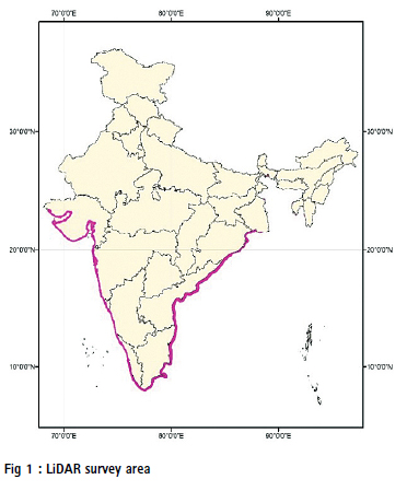
Airborne topographic LiDAR scanner (ALS) integrated with medium format single CCD digital camera (MFDC) is utilised off late very extensively in large scale geospatial database generation projects to produce precise high resolution (HR) DTMs. LiDAR has capability of delivering 3D point clouds of terrain and object surfaces (DSM &DTM) height information in short duration of time with high spatial density to an accuracy of decimeter. MFDC data is used to generate large scale (LS) planimetric maps from orthoimages (Gopala Krishna et al. 2013). National Remote Sensing Centre (NRSC), ISRO has delivered the HR DTMs, LS Topo maps, and 2.5D building database, which were produced using data acquired by ALS LiDAR sensor and Medium format digital camera along the Indian mainland coastline covering ~5000 km with an extent of area ~24000 sq. km (fig:1) having inland coverage of 2km from the coast including major estuary, creeks for INCOIS organisation ( Indian national centre for ocean information services ), GOI under Ministry of Earth sciences located at Hyderabad, India. This data is utilised at the Tsunami warning centre as one of the inputs in building Tsunami inundation models for different earthquake scenarios possible on the east coast(Andaman-Sumatra subduction zone, Bay of Bengal sea ) and west coast(the Makran subduction zone, Arabian sea (Shailesh Nayak et al. 2008). Also utilised these datasets to prepare and update multi-hazard (Tsunami, Cyclones, floods) vulnerability maps representing vulnerability, risk, and hazard information together.
Tsunamis and cyclonic storms generate massive water wave surges at the sea coast in different amplitudes. These surges cause seawater flooding into the land as much as 1-2 km or even more, resulting in loss of human life and damage to property. INCOIS has developed Tsunami & storm surge models to predict the inundation along the Indian coast using HR DTMs and other inputs (Srinivasa Kumar et al., 2012). These models help in the preparation of geospatial information, which indicates the potential areas which are affected due to tsunami and cyclone inundation at the cadastral level (Mahendra et al. 2011 & 2010, Srinivasa Kumar et al. 2010). These inputs help disaster management teams of central-and state-level departments to utilise in mitigation planning, rescue and evacuation operations.
The accuracy of inundation model prediction is directly related to the quality of the topography data apart from other inputs. To provide the inundation information at cadastral/ parcel level for coastal areas covering a large area with flat lands with fewer undulations and cluttered with small buildings requires highresolution topographic data sets and large-scale planimetric information. High-resolution data acquired with decimeter accuracy in position and elevation by LiDAR and MFDC sensors were used in delivering largescale topographic and planimetric data in this project. Seamless Hydro enforced and Hydro conditioned DTMs in MSL datum with elevation accuracy of 0.35m having grid spacing of 5m and contour with 1m intervals were generated to utilise them in inundation modelling for the entire mainland of Indian coast. Produced Large scale planimetric maps in 1:5000 scale (generated from 0.50m GSD orthoimages produced from MFDC digital camera images integrated with LiDAR sensor) having information layers of built-up area, transportation network, communication & power infrastructure, hydrographic features etc., Also generated 2.5D building database, accurate to 1m height which helps in identifying relief shelters, buildings. This building database is also used to simulate inundation by different water levels to plan rescue operations in case of evacuation.
Indian coast is covered with flat to highly undulating terrain with various landforms such as Sand beaches, Mudflats, marshy lands, rocky areas, Mangroves, agricultural farms, aquaculture farms and small villages to urban areas. Acquisition of topographic data optimally with LiDAR, which is operated in the NIR region at 1064nm wavelength where water absorbs the incident energy completely (land covered with waterbodies and wetlands) without sun glint, without dead zones in high urban areas using aircraft in a narrow corridor of 2 km width along the coast throws up various challenges to planning, acquisition, ground teams. This article covers how LiDAR technology and photogrammetry are utilised in the realisation of seamless HR DTM, large-scale 2D geospatial data and 2.5D building database for such complex terrain and land features and its end application for Indian coast.
LiDAR survey planning and acquisition
Flight planning
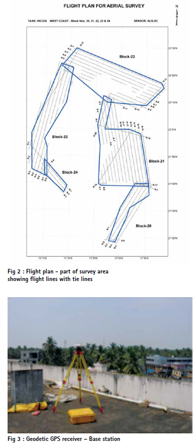
The total project area to be surveyed is medium in size (~24000 sq. km). Even though the area to be acquired appears to be less in terms of numbers, the area distribution is with a very narrow region of 2kms along the coast, having many bends and discontinuities due to creeks and rivers. To generate seamless LiDAR DTM, a LiDAR survey was planned to cover in several blocks (small areas of near to rectangular polygons) with overlap. Ensured 10% of overlap between block to block during planning. Tie flight lines were also planned to ensure the geometric fidelity of data. Finding the features which are required to tie the blocks is difficult as 40% of the area is covered with sand / beaches and 10% marshy/wetlands. Hence extra area with varied buffer to AOI is taken, so that land features are available to generate tie points/lines (fig:2). To georeference the LiDAR data to the decimeter accuracy by using direct geo-referencing (DG) technique, planned boresight calibration flights before commencing the acquisition over calibration sites located at NRSC, Hyderabad along with other system health checks regularly to ensure the overall system performance. Configured the LiDAR sensor and digital camera to acquire both the data simultaneously along with other reference positioning systems, GPS and IMU. Direct geo-referencing of LiDAR data & camera data is carried out using the EO parameters derived from GPS & IMU integrated positioning data. Orientation of Camera data with EO by DG provides positional accuracy of 2-3 pixels. However, sub-pixel accuracy in position is required to generate seamless orthoimages and to maintain the position of planimetric features in the camera with DTM height information. To meet this challenge of geo-referencing of LiDAR point clouds with images precisely, full control points from LiDAR data were planned optimally. Control points collection over small agricultural bunds, edges of painting marks, small bushes in case of remote /vegetative areas etc., from LiDAR data was devised.
Acquisition of data in wide strips reduces the number of flight lines to be acquired and this inturn helps in processing of data with less effort and time. To optimise the flight lines, which are required to cover the entire survey area, including tie lines, a flying height of 3000m was planned to suit the requirement of height accuracy & point spacing with the maximum wide swath possible for each run. Planned 50 deg field of view (FOV) of laser scanner by considering all the requirements said above with 10-15% side lap between flight lines to get optimum flight lines(fig:2).
Ground surveys
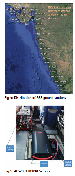
Direct geo-reference of both LiDAR & DC image data require exterior orientation parameters and these are derived using post-processed airborne kinetic GPS (KGPS) & IMU data. It is required positional accuracy of 10-15 cm and 0.005deg attitude accuracy to meet the sub-meter location geolocation accuracy of both the data sets, i.e. LiDAR & camera. Kinematic GPS positioning accuracy is poorer due to inherent errors present in data. To remove the errors and improve the accuracy of kinematic GPS data, differential GPS processing is carried out during post-processing by using static GPS data collected on the ground simultaneously during data acquisition. Static GPS data is recorded at 2Hz in the field with close baseline separation. Operated GPS base station during data acquisition optimally along the survey area at 50km spacing as shown in fig: 3 and 4.
Geo-referenced LiDAR data by kinematic GPS data is with respect to the WGS84 ellipsoid coordinate system. To derive the hydrologically corrected DTMs with reference to MSL datum from LiDAR data need precise geoid undulations’ N’ data which is accurate to 5-10cm. As India does not have geoid undulations to the accuracy of sub decimeter, field methods are employed in this task. In the field, WGS84 height (h) and MSL height (H) is collected at the exact location using geodetic GPS & levelling instrument, respectively, to derive geoid height. The geometric method (N=H-h) is used in the derivation of geoid undulations. In field, the geoid undulations data (h, H) is collected at the regular spacing of about 10km. SOI (Survey of India) established a sparse GT BM network with varying spacing available across India. Those GT BMs were taken as a reference to extend the levelling network by traversing several km (~8000 km) along the coast to collect MSL heights at selected locations. MSL heights are collected on flat surfaces such as platforms, the centre of the road where culverts exist, playgrounds, and open lands. GPS height data collection in the field has been entirely avoided by implementing a novel approach of collecting from LiDAR point’s average height at flat surface in WGS84 heights instead of using a GPS instrument in field. This methodology has not only reduced the field efforts and contributed in removing the bias errors present in LiDAR data.
Acquisition
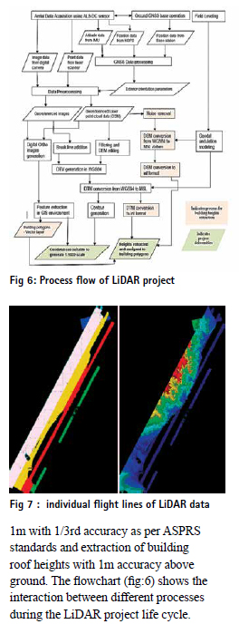
Acquired the entire coastal area of ~24000 sq. km in a duration of 10 years. During this period, LiDAR sensors and camera technologies have been changed in terms of accuracy, point spacing, positioning systems, camera total number of pixels, GSD etc. During the span of the entire data acquisition period, three models of LiDAR sensors & cameras were inducted. LiDAR sensor ALS50, ASL50-II, ALS70 and cameras spectrum, rcd105, and rcd30 were used during acquisition. Technologies have been improved from ALS50 to ALS70 fig (5) in terms of pulse repetition frequency of 50 kHz to 500 kHz, i.e. ten times. Mission planning and sensor controlling, pre-processing software have also been improved. These technological transformations in sensors performance in terms of PRF, mirror scan rate, and range accuracies have helped in acquiring the data optimally. Adoption of tightly coupled systems in place of loosely coupled systems enabled to reduce the turn time in flights. Improvements in high PRF enabled acquisition data at higher point density from the same altitude.
Performance checks and boresight calibration is required to be carried out for each installation of LiDAR and camera prior to the acquisition of data to ensure quality data. LiDAR and camera sensor’s critical parameters and their performance were evaluated by conducting flights over calibration sites in and around Hyderabad city. Test flights were conducted at project flying height over calibration site to check the positional accuracies are meeting the planned requirements. Flying over project site was carried out mostly after the post-monsoon season to acquire the cloud-free images and LiDAR data with minimal flying efforts.
Data processing
To generate a seamless dataset for the survey area, which is spread across several longitudes from 68o to 88o and falls in UTM zones of 42 to 44, requires initial planning to avoid edge matching errors during data pre-processing, datum conversions and features extraction. Processing of LiDAR and camera data which are in sensor coordinates to map coordinates and conversion of ellipsoid heights to MSL heights, requires several transformations. The following steps were followed in the processing of LiDAR and digital camera data sets to generate HR DTMs in MSL datum with 35cm accuracy, 2D planimetric geospatial data in 1:5000 scale with an accuracy of 0.25mm of map scale and contours of 1m with 1/3rd accuracy as per ASPRS standards and extraction of building roof heights with 1m accuracy above ground. The flowchart (fig:6) shows the interaction between different processes during the LiDAR project life cycle.
LiDAR data processing steps
• Calibration of boresight angles
• Lever arm measurements
• Geo-referencing • Strip adjustment
• Ground classification
• Incorporation of 3D brake lines
• Geoid undulations modelling
• MSL data conversion
Camera data processing steps
• Raw to image data with Radiometric corrections
• EO parameters generation
• Boresight angles calibration
• Orthoimages generation
• 2D Geodatabase generation.
Boresight-Calibration: Misalignment angles ( Δroll, Δpitch, Δkappa) between laser scanner and IMU governs the final accuracy significantly. Not accounting for these angles may induce significant positional errors in meters in some cases (JagannadhaRao et al., 2013). Hence misalignment angles are to be determined very accurately. In the determination of these values, the field boresight calibration method is carried out using the data collected over the flat and slopped surface area in a particular pattern depending on the type of error to be computed. Flight lines over flat surfaces flown in opposite are used to determine roll error, flight lines acquired in opposite directions across over sloped surfaces are used to determine pitch error and to obtain heading error; parallel flight lines are used. These values are to be determined with accuracy better than 0.001 radians. Inclusion of spatial separation (lever arms) distance between different sensors, i.e. IMU and laser scanner and IMU and GPS, is also required during the computation of position accurately. These values (ΔX, ΔY, ΔZ) are determined in the field very precisely using ground instruments such as total station in less than 1cm error.
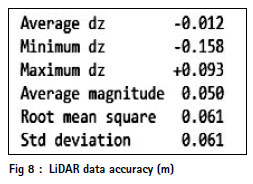
These calibration flights are carried out for each installation to determine misalignment values apart from verification of other system parameters, viz. encoder latency, torsion angle of scanner shaft, laser range error bias due to electronics delay. LiDAR data which is corrected for all the above systematic errors, are verified against ground control points which are collected over a flat surface (airport runway) to determine absolute accuracy. Seventy control points spread across uniformly on an airport runway of a 2km stretch located at Hyderabad are used to verify absolute accuracy (fig:8).
Camera data pre-processing: Similarly, the camera is also to be calibrated for boresight angles and lever arms. During pre-processing stage i.e conversion of raw camera data to the image, radiometric calibration coefficients are applied to remove the CCD non-uniformity and camera lens distortions coefficients and principal point offset are applied to remove correcting geometric distortions. Subsequently, exterior orientation parameters which are required for orientation and geo-referencing of camera data are deduced using kGPS and IMU combined positional data.
LiDAR data pre-processing: Calibration values determined, i.e. misalignment angles and lever arms, range errors from test flights are applied on data acquired over surveyed data during geo-referencing of laser data. The ultimate objective of LiDAR data processing is the generation of seamless data sets (fig: 7&9). LiDAR data which is acquired in multiple days, have positional errors at side overlap regions due to geo referencing errors induced by varying kGPS positional accuracy. The quantum of positional error depends on the geometry of satellites which varies from time to time with respect to location. The planimetric and height accuracy of LiDAR points differs from sortie/flight to flight due to these GPS errors. Hence there are position errors exist between each flight line overlap in the order of decimeter (positional variation can be observed at the overlapping region of flight lines). To determine these variations between flight lines and minimise the errors, tie flight lines are also acquired. These tie lines connect all the regular flight lines flown together parallel to each other. Critical planning is required to connect regular lines optimally during flight planning. These tie flight lines help in strip adjustment process to determine positional, angular and scale errors present in data for each flight line. To compute the positional errors, Tie lines/tie patches are generated using the least squares fitting method at the common features present in overlap regions and side laps. Using the tie lines identified for different features, differences in positions, rotations and scale are computed. The computed values are used to adjust the LiDAR flight lines together to generate seamless data with 1 to 2 cm.
DTM generation: To generate DTM from LiDAR point cloud, bare earth points pertaining to terrain have to be separated out (fig: 10). Also, ground points are to be added where ever points are missing along the edges of features such as stream centerlines, canal edges and also points are to be removed where hydrographic features are passing below the cultural features such as roads, rail, and culverts. To obtain terrain points from the point cloud, a progressive densification classification algorithm is used. This algorithm works with 75% to 85% accuracy in flood plain flood-prone areas where most of the lands are flat to moderate and have agricultural crops and short vegetation such as scrubs. The reaming points are either unclassified or misclassified. Usually, classifying the unclassified points, misclassified points, and the addition of extra points in the form of break lines are done manually. This process consumes a lot of processing time and it is a bottleneck in the generation of the DTMs in quick time.
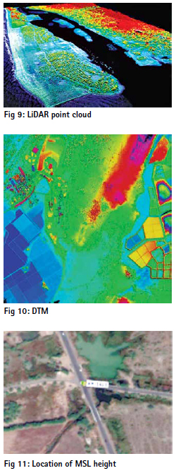
DTMs generated by the above process are in the WGS84 datum, and transformation to the MSL datum is required to make them hydrologically enforced and conditioned. To convert LiDAR DTMs which are in WGS84, to MSL datum, geoid undulations data which is better than decimeter, is required. India does not have such precise geoid information for the project survey area (along the coast). Hence data collected using the ground method was employed. Geoid undulation is derived by subtracting the terrain height collected at the exact location in WGS84 datum and MSL datum. The field method involves enormous effort and costs to obtain levelling and GPS data. In this project, MSL heights were collected using levelling instrument, and WGS84 heights were collected in the lab from LiDAR data. Optimised the collection of WGS84 heights with GPS by establishing a new approach in which WGS84 Heights are collected from LiDAR data itself, where flat land is present. As identification and collecting WGS84 height at a particular LiDAR footprint location and collecting MSL height exactly over the LiDAR point is difficult, flat ground patches available in the field are used for MSL height. Flat patches such as platforms, playgrounds, flat Road centers, open Grounds etc., are opted for during data collection (fig:11). This approach has reduced the field component effort and enabled the reducing project timelines. DTMs which are corrected in all aspects are stored in Geotiff format with coordinate system of UTM to use in final hydro modelling, as well as generated orthoimages from digital camera data which is oriented very precisely to one-third of pixel by using photogrammetric block adjustment methods at 50 cm resolution. Orthoimages which are corrected for terrain relief were used further to capture 2D planimetric information of cultural, natural features position, boundaries at 1 in 5000 scale by visual interpretation methods digitally in GIS environment as it requires cartographic quality and positional accuracy of 0.25mm of map scale( fig:12).
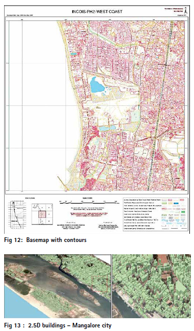
To extract rooftop heights of 2.5D buildings (fig:13) with respect to MSL and AGL(above ground level), building vector layer captured from MFDC orthoimage, LiDAR DSM and DTM are used as input(Sadasiva Rao et al., 2013). A tool was developed in-house to automatically extract the MSL height and AGL height of the building using the raster DSM and DTM. For each 2D building boundary, a height value is assigned based on the metrics (Majority and Median) computed using DTM and DSM pixels within the footprint. To deduce rooftop heights with respect to MSL datum, the majority of the DSM pixels height is assigned as it takes care of roof height errors induced due to the presence of adjacent overlapping vegetation, parapet walls, lift rooms and water tanks etc. The median of the pixels height of DTM is used to compute the terrain heights within the footprint as it takes care of the slope of the terrain. AGL height is derived by subtracting DTM median heights from DSM majority heights.
Data utilisation
The products generated from ALS & MFDC data sets i.e DTM, orthoimages, 2.5D buildings were used in the following applications by INCIOS along with other ancillary data sets.
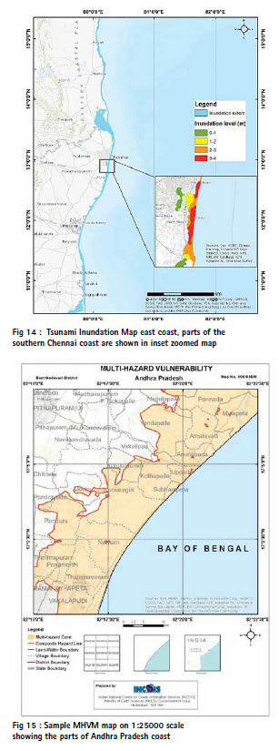
Tsunami Inundation modelling: The high-resolution topographic data from Airborne LiDAR and Cartosat-1 satellite DEM were merged with the available coastal bathymetry as an input for the coastal inundation modelling. The 26 December 2004 Indian ocean tsunami generated due to Mw 9.3 magnitude earthquake scenario was simulated on these data using the seismic parameters (Usha et al 2012; Iyyappan et al., 2018). The simulation was carried out in the ADCIRC model by providing the initial condition (water displacement) estimated as per Legg et al. (2004). The results of the Tsunami inundation of the east coast of India are provided in Fig14. The different run-up heights on the coast were recorded depicting the risk of tsunami exposure in the coastal zones. These maps help in the planning of tsunami disaster.
Multi-hazard Vulnerability Mapping (MHVM): The purpose of multi-hazard vulnerability mapping (MHVM) is to identify the most vulnerable and high-risk areas due to oceanogenic disasters. The multi-hazard mapping was carried out using the parameters of sea level change, shoreline change rate, elevation contours derived from ALS and Carto-DTM, extreme water level from tide gauges and the return periods (Mahendra et al., 2010, 2011 & 2021). These parameters were synthesized to derive the composite hazard line. These maps represent the coastal inundation caused due to Tsunami, cyclone, flood. The hazard and vulnerability maps are highly useful in coastal zone planning in order to prepare for disaster events and manage the situation during the disaster. These maps are also useful for future developments activates as well. This MHVM mapping was carried out for the entire mainland of India on 1:25000 scale. An atlas comprising 929 maps was prepared. A sample map of the atlas was given in Fig15.
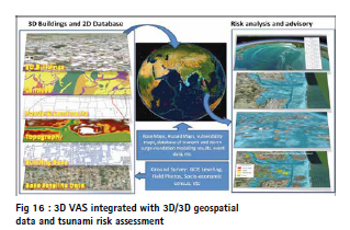
3D GIS Mapping: The geo spatial database generated using the ALS and digital camera images data were integrated into the 3D/2D data visualization and analysis system (3DVAS) desktop application. This 3DVAS application is integrated with the terrain database generated using DTM draped with aerial images. Further, building bases provided with the building height were used to visualize in the 3D GIS environment based on their respective heights. This provides a virtual 3D view of the entire Indian mainland coast. The major purposes of 3D GIS are to visualize and effectively communicate the inundation threat at the street level and to plan evacuation routes. 3DVAS can also simulate tsunami inundation and on-thefly generate the building level risk maps. Example images of 3DVAS integrated with 3D GIS data and inundation modelling capability are provided in Fig16 .The datasets generated using the ALS topography and orthoimageries are proved to be highly useful for the microlevel disaster assessment and planning.
Conclusions
Datasets acquired from Airborne lidar and digital camera enabled to generate high resolution digital terrain models with an accuracy of 35cm, large scale maps in 1:5000 scale and 2.5D building database for narrow corridor of 2km along the entire Indian main land coast of ~5000 km for an extent of ~24000 sq.km covered with complex features and terrain.
Data has been utilised in generation of tsunami models at local scale for different magnitudes of earthquakes, preparation of multi hazard vulnerability maps for oceanogenic disasters, to assess disasters at micro-level and planning the mitigation.
References
Gopala Krishna PVSSN et al. 2013. Generation of high resolution dem for inundation studies using airborne lidar, ISPRS workshop, WG VIII/1, WG IV/4. Iyyappan M, Usha T, Ramakrishnan SS, Srinivasa Raju K, Gopinath G, Chenthamil Selvan S, Dash SK and Mishra P. (2018) Evaluation of tsunami inundation using synthetic aperture radar (SAR) data and numerical modeling. Nat Hazards 92, 1419–1432. https:// doi.org/10.1007/s11069-018-3257-4.
Jagannadha Rao CVKVP, et.al 2013. Airborne lidar data characteristics – issues and solutions, ISPRS workshop, ISPRS WG VIII/1, WG IV/4
Kulp, S.A., Strauss, B.H. 2019. New elevation data triple estimates of global vulnerability to sea-level rise and coastal flooding. Nat Commun 10, 4844
Legg MR, Borrero JC, and Synolakis CE (2004) Tsunami hazards associated with the Catalina Fault in southern California. Earthq Spectra 20(3):917– 950. https://doi.org/10.1193/1.1773592
Mahendra RS et al. 2010. Coastal Multi- Hazard Vulnerability Mapping: A Case Study Along The Coast of Nellore District, East Coast of India Italian Journal of Remote Sensing – 2010, 42 (3): 67-76
Mahendra RS, Mohanty PC, Bisoyi H, Srinivasa Kumar T, Nayak S 2011. Assessment and management of coastal multi-hazard vulnerability along the Cuddalore—Villupuram, east coast of India using geospatial techniques. Ocean and Coastal Management 54(4):302–311
Mahendra, R.S., Mohanty, P.C., Francis, P.A., Sudheer Joseph, Balakrishnan Nair T. M. and Srinivasa Kumar T. 2021. Holistic approach to assess the coastal vulnerability to oceanogenic multi-hazards along the coast of Andhra Pradesh, India. Environ Earth Sci, 80, 651. https://doi. org/10.1007/s12665-021-09920-z
Mahendra, R.S., Mohanty, P.C., Srinivasa Kumar, T., Shenoi, S. S. C., and Shailesh Nayak. 2010. Coastal Multi-hazard Vulnerability Mapping: A Case Study along the coast of the Nellore District, Andhra Pradesh, East Coast of India. Italian Journal of Remote Sensing: Vol. 42, Issue 3, pp. 67-76. https:// doi.org/10.5721/ItJRS20104235
RS Mahendra et al. 2011. Assessment and management of coastal multihazard vulnerability along the Cuddalore Villupuram, east coast of India using geospatial techniques Ocean & Coastal Management 54 (2011) 302-311
SadasivaRao.B et.al 2013. Generation of 2.5D buildings using airborne lidar and medium format digital camera data for Indian coast, ISPRS workshop, ISPRS WG VIII/1, WG IV/4
Shailesh Nayak et al. 2008. Addressing the Risk of Tsunami in the Indian Ocean, Journal of South Asia Disaster Studies, Vol. 1 No. 1 November (2008) 45-57.
T. Srinivasa Kumar et.al 2010. Coastal Vulnerability Assessment for Orissa State, East Coast of India, Journal of Coastal Research vol.26 no. 3, 523–534.
T. Srinivasa Kumar et.al 2012. Successful monitoring of the 11 April 2012 tsunami off the coast of Sumatra by Indian Tsunami Early Warning Centre, Current Science · October( 2012)
Usha T, Ramanamurthy MV, Reddy NT, Mishra P (2012) Tsunami vulnerability assessment in urban areas using numerical model and GIS. Nat Hazards 60:135–147. https://doi.org/10.1007/s11069-011-9957-7
Acknowledgements
The authors would like to acknowledge the support provided in realisation of the project by former Directors of NRSC viz. Shri.Santanu Chowdhury, Dr YVN Krishna Murthy ,Dr V K Dhadwal, Dr V Jayaraman and Dr K Radhakrishnan . Direction and guidance provided by former NRSC Deputy Director, Sri Raghu Venkataraman , ASDM&OA are acknowledged. The Data acquisition, LiDAR Data processing, Ground surveys, Flight planning, Quality Assurance teams and their Heads contributions are duly acknowledged.


 (2 votes, average: 2.50 out of 5)


Leave your response!