| Navigation | |
Driver assistance and awareness applications
This paper introduces the use of the map database as a sensor in driver assistance and awareness applications |
|
 |
|
|||||
Driver Assistance and awareness applications such as Adaptive Cruise
Control (ACC) and Forward Collision warning need to identify the
primary target in the host vehicle lane,which requires accurate estimation
of the geometry of the road between the host and the target vehicle.
Curve Speed Warning (CSW) also requires determining the geometry
of the intended driving path to warn the driver of going too fast for an
upcoming curve. Predictive adaptive front lighting can use the predicted
road geometry to swivel the headlamps in the road curvature direction. Route
guidance can use the MLP data to warn the driver of a potential mistake
in following the calculated route. Map matching can use this data to
improve its performance at ambiguous branching areas where the map
matching position confi dence is low. The MLP is primarily determined
by fusing vehicle signal data, lane marking information, and map
database attributes. Real road results show an impressive benefi t and
performance from this approach.
Path prediction
The most likely path determination is achieved by designing a Look Ahead
Module (LAM) that looks forward from the vehicle position to the lookahead
distance. The LAM determines the most probable path of the vehicle
using information from vehicle positioning, lane information, lateral
velocity, and vehicle signals and state. The most probable path and
other possible alternate paths can be predicted using the vehicle’s
travel direction, the direction of the road, the vehicle lane, and
the predicted directional change. This information is evaluated
using a Cost Function to weight each parameter with respect to
the influence that the parameter will have toward predicting the
vehicle’s most probable path. The LAM also uses the look ahead
distance to assemble a candidate path subset that is
projected out to a selected distance from the vehicle’s current position.
If only one possible candidate path exists, it will be returned with 100%
confi dence. Otherwise, a list of all possible candidate paths (and
their associated confidence levels) within the look-ahead distance
will be calculated. The most probable path, i.e. the candidate
path with the highest confi dence level, is passed to the application
(for example: CSW algorithm).The MLP can be calculated using
the map database information such as the shape point coordinates
and the advisory speed or speed limit Map attributes, the lane
boundary types from a vision system if available, and the yaw
rate, vehicle speed, throttle, brake,turn signal from vehicle sensors.
Example: Road branching scenario
In the road scenario shown in Fig.1, if the driver initiates a right turn signal
before branching then this represents an indication that the driver intends
to branch right, or to perform a lane change. If the boundary type of
the driving lane indicates that the vehicle is not in the middle or left
lane, then it is more probable that the driver will take the upcoming right
branch. The probability of taking the branch is a function of the vehicle
location from the branching point.
Driver assistance and awareness (DAA) applications
Visteon has used the GPS and map database as sensors. In the USDOTfunded
Road Departure Crash Warning – Field Operational Test[1], Visteon developed Curve Speed
Warning (CSW) functionality using a commercial navigation system
and map database. The CSW system warns the driver when the vehicle is
traveling too fast for an upcoming curve by processing the map database
geometry and attribute information. CSW uses the navigation system to
place the vehicle position on the map, and then, the CSW algorithm looks
ahead on the map, extracts all possible driving path candidates, determines
the intended driving path, performs a curvature calculation on the geometric
data of this path, and fi nally performs a threat assessment based on the
vehicle speed and road curvature ahead.
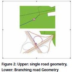
Figure 2 shows both single
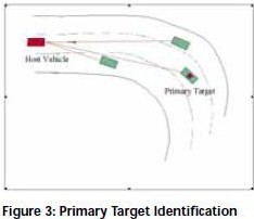
road and branching road geometries. Adaptive cruise control and forward
collision warning systems can use the MLP calculation to determine the in
lane primary target. The functionality of ACC and FCW depends solely
on determining the primary target in the host vehicle lane (Fig. 3).
This requires accurate estimation of the road geometry between the host and
the target vehicle. The host vehicle controls its speed based on the
range and range rate measurements of this target. If the target becomes
out of the host vehicle path, the ACC system resumes to regular
speed control (cruise control).
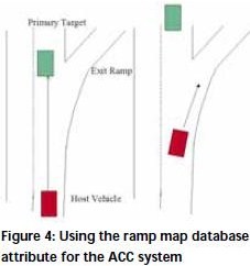
An undesired “resume” could happen
in an exit ramp scenario (Fig. 4) where the host vehicle starts to
accelerate to the set speed toward a low speed ramp. Such undesired ACC
performance could be prevented by provided the ramp information from
the map database ramp attribute. Visteon’s Predictive Adaptive
Front Lighting System (PAFS) uses the MLP calculation and
processing to swivel the headlamps based on the upcoming MLP
calculated curvature as shown in Fig 5. Swiveling the headlamps
beam toward the upcoming road increases the visibility in that road.
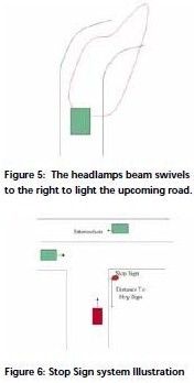
Another application that can use the map database information is stop sign
warning (SSW). The SSW informs the driver for an upcoming stop sign
at a designed “time to reach”. The stop sign information is an attribute
in the current commercial map database. Illustration of the system
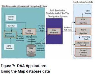
functionality is shown in Fig. 6. Figure 7 illustrates the architecture
of map database processing for the DAA applications.
There are three main pieces in this architecture: first, a commercial navigation system
module that provideson the map, second, the path prediction module that selects
the MLP and performs a curvature calculation, and third the application
module which uses the MLP information and other inputsto perform its function.
Land vehicle navigation(LVN) applications
Route guidance is an essential feature in current land navigation systems.
In this navigation feature, the driver feeds the navigation
system with the desired trip destination. The route guidance algorithm
calculates the route for the driver to follow. The driver may make mistakes
in following the intended(calculated route),and the route guidance system
will have to adjust its instruction to correct this mistake. This corrective
instruction will result in the driver having to spend extra time and the
vehicle to consume more fuel to perform this correction. In addition this
instruction may confuse the driver and cause hazard situation.
A predictability feature can be added to the route guidance
algorithm if the instantaneous MLP (IMLP) is calculated using the
MLP algorithm. If the IMLP doest not match the pre-calculated route,
the route guidance system may advise the driver of potential mistake in
following the pre-determined route. Map matching can also use the
MLP information in an ambiguous road geometry scenario where the
combined GPS/Map accuracy is not adequate to place the vehicle on the
right road with a high confi dence. The MLP information provides the
map matching algorithm with the expected position after the branching.
This information can either increase the history weight (MLP matches
the expectation that the vehicle will continue on the same road), or reduce
the history weight (MLP indicates that the driver will take the branch).
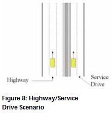
The Service drive/Highway road scenario shown in Fig. 8 presents a
diffi cult challenge for map matching due to the lack of map matching
excitation. Both roads are parallel and close to each other. The heading
angle/yaw rate information is not helpful, and the combined GPS/Map
accuracy is not adequate to place the vehicle on the right road with a high
confi dence. A combination of the vehicle speed and the posted/advisory
speed map database attribute can help in resolving such ambiguity.
Map database requirement as a sensor
Current commercial map databases are designed for navigation purposes.
The accuracy of a commercial map is investigated in [2]. The accuracy
of these maps is suffi cient for the navigation application in a large
variety of road scenarios. However,they sometime fail in road scenarios
like service drive/highway, highway/exit ramp, fork, complex overpasses,
and mountain area/single road. All of these scenarios could lead to placing
the vehicle on the wrong road or off the road. The absolute and relative
accuracies have been improved by the continuing replacement of
the old map database shape points with ADAS quality shape points.
However, the accuracy of the ADAS map is still inadequate in many of the
branching scenarios and scenarios where the 3D information is required.
For the path prediction algorithm, placing the vehicle on the wrong
road segment results in incorrect set of the road candidates, which leads
to an incorrect MLP. In cases with correct vehicle position, the relative
accuracy is the determining factor in path prediction. An accurate relative
placement of the shape points along the MLP means an accurate curvature
distribution along this path. The rules and method of creating the map
database (ADAS or older) can lead to very low relative accuracy in some
road scenarios. An example of this is the connectivity rule, which requires
of adding extra shape points solely for connectivity purposes. These
added shape points are not part of the road geometry and can lead to
wrong curvature values along the path. Other rules like the merging
rule in connecting divided roads to undivided roads or vice versa,
or connecting an on ramp with a main road can also lead to wrong
representations of the path geometry. Considering the map as a sensorrequires,
as with any other sensor,having its error sources defi ned and modeled.
It is also required to have corrective/updating capability.
Furthermore, information such as height and super elevation are
required to extend the usage of the map for other automotive applications.
Sample navigation system interface/results
The sensing capability of the map provides detailed information of the
instantaneous road segment and the road segments ahead. An example
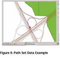
of that is shown in Fig. 9. In this figure a vehicle (red arrow inside the
circle) is approaching an exit ramp branching. The blue road is path 1
which consists of two segments: the segment that the vehicle is currently
on (segment before branching), and the straight (highway) segment after
branching. The blue road segment followed by a magenta segment is
path 2, which consists also of two segments: the segment that the
vehicle is currently on (segment before branching), and the curved
(ramp) segment after branching. The path set in Fig. 9 is an example
of how the navigation unit may output the map sensor data.
The path data could be described by a number of curvature points along
a look-ahead travel distance of the corresponding path. Each
curvature point can be described by global latitude and longitude
coordinates, vehicle centered true north/east coordinates, curvature
value, confi dence value, number of lanes, and travel distance
from the vehicle location. Figure 10 shows application specifi c
path data. In this scenario, the path prediction algorithm senses
that the driver is most probably taking the exit ramp to the right.
The curvature data and other data of the MLP are sent to the CSW
threat assessment algorithm, which may initiate a CSW warning at
some distance before branching.
Conclusions
The Map database can provide detailed information about the road
segment at the vehicle position and the road segments ahead of the vehicle.
This information, when processed, can be used for driver assistance and
awareness applications such as ACC,FCW, CSW, PAFS, and SSW. In order
to optimally use the map database, its error sources should be defi ned and
modeled. In addition, it requires map corrective/updating capability due
to the changing nature of the roads.Furthermore, information such as
height or elevation and super elevation are required to extend the usage of the
map for other automotive applications.From a commercialization
perspective, a standardized navigation system interface is recommended.
References
[1] NHTSA, “Status Report on USDOT Project “An Intelligent Vehicle Initiative
Road Departure Crash Warning Field Operational Test”. www-nrd.nhtsa.dot.gov.
[2] T. Pilutti, F. Ibrahim, M. Palmer, and A. Waldis, “Vehicle Position Analysis
of a Commercial Navigation System”, SRR-1999-0169, November 17, 1999.
My Coordinates |
EDITORIAL |
|
His Coordinates |
MAJOR GENERAL M GOPAL RAO, IRWIN ITZKOVITCH, CLEMENT
|
|
News |
INDUSTRY | GPS | GIS | REMOTE SENSING | GALILEO UPDATE |
|
Mark your calendar |
FEBRUARY 2006 to NOVEMBER 2006 |




 (No Ratings Yet)


Leave your response!