| GNSS | |
Assessment of GNSS-based systems for railways safety
Under consideration of current approval processes in railway environment based on standards like EN 501026 RAMS-process (reliability, availability, maintainability, and safety) and available GNSS standards like EN 16803-1 and ETSI TS 103 246-3, the described approach presents a possible high-level process for assessment of GNSS based systems |
 |
|
 |
|
 |
|
European Railway Traffic Management System (ERTMS) is the European standard for the Automatic Train Protection (ATP) and command and control systems. ERTMS is a safety system enforcing compliance from trains with speed restrictions and signalling status.
In last years, GNSS was acknowledged as an important sensor system for implementation of ERTMS in field of virtual balises., This document presents an approach for qualification of GNSSbased reference equipment for assessing GNSS equipment to be later used in trains for safety critical applications e. g. identification of moving blocks. Main focus of the document is the underlying assessment process according to the regulations required in an accredited laboratory for GNSS like NavCert as the only laboratory accredited in Europe in the scope of GNSS.
1. Introduction
In the context of Intelligent Transport Systems (ITS), railway domain depends on usage of GNSS for both safety-critical and non-safety-critical applications. As an example, project CLUG (Certifiable Localisation Unit with GNSS; http://clugproject.eu/ fr) can be cited which develops a new approach for train localization. Aims of the CLUG project are:
▪ to provide position, velocity, and acceleration of train
▪ to replace or enhance board equipment (e.g., odometry, balise reader)
▪ to foster new concepts as Moving block, European Rail Traffic Management System (ERTMS) L3
▪ to prototypical certify prototype based on project internal standard
However due to missing mapping of GNSS to functional safety requirements of rail so far, balises are still main reference for absolute positioning. There is an emerging concept of virtual balises, which are virtual points, recorded in an embedded geographic database. These points could be e.g., coordinates of real physical balises. Basic idea is to derive deviation of train positioning solution obtained by GNSS to this database of points. n same telegram as a physical balise can be sent from “virtual” one. This enables a cost-effective modernization and a significant increase in efficiency of monitoring systems. For usage of such systems, qualification is necessary. In following, qualification for such systems will be presented on a high level.
2. Assessment process for measurement equipment in laboratories
This section provides an overview of assessment process within laboratories. Process is based on laboratory standards like ISO 17025 and is split here into two sections:
▪ Development of test scheme with a qualification of measurement equipment
▪ Testing with measurement campaigns according to specifications of test schemes
2.1 Development of assessment scheme
In preparatory work, first scope of assessment is defined. In context of this paper scope is assessment of GNSS based positioning systems. Based on scope and analysis of available standards and/or regulations is conducted which need to be acknowledged in later process. These referring standards and regulations define metrics for assessment. Usually, a general metric overview is given by standards and regulations. Sometimes an adjustment of metric is needed to cover specific topic of assessment. In only a few cases metrics definition from standards and regulations can be taken over one by one. If no standards and/or regulations exists, a laboratory internal “standard” shall be defined and used.
Next step is definition and description of measurement background and observables. Thereby measurement background describes initial process of how observables are measured and how observables are connected to metrics. Standards and regulations shall be considered here because these set certain requirements and limits for these two topics. It shall be noted for laboratory tests only calibrated and validated equipment is allowed to be used. If no calibration is possible laboratory needs to define an own process instead. This serves metrological traceability of test case and test scheme.
Based on previous work an error analysis shall be conducted, whereby first an overview of all possible impacting factors based on measurement background shall be created. Based on quantification of listed factors an expected error range for measurements can be given. This shall be compared with initial metrics requirements. If a deviation is detected measurement process shall be refined and succeeding process repeated. Hereby also new requirements for measurement can be defined like for example environmental conditions.
Based on these outcomes and to refine complete process a statistical analysis shall be conducted. This process can cover topics like for example a sample analysis to determine if in defined measurement process results can be calculated with sufficient probability and quality.
After these steps, verification of complete process and method needs to be conducted to ensure its feasibility, reliability, and quality. This can be done via different methods like audits, simulations, etc. If no anomalies or deviations were detected during this process final definition of assessment process through its test cases, criteria, which are summed up in test scheme, is therefore completed. Or wise, depending on detected deviations, previous process on different levels needs to be refined and completed again. As last step, an independent review of process shall take place to ensure its integrity. With this, assessment scheme can be released and after training is used.
2.2 Implementation of assessment process
In general, for implementation process, stated requirements from test scheme shall be followed. Additionally, following points shall be acknowledged:
▪ Identification of test equipment, test samples and documentation of test process and test results
▫ For assessment process and its implementation, it is essential, all used equipment and provided samples can be later identified to provide reliability, reproducibility, verifiability, and traceability. This applies also to measurement data, provided documentation, test process, interim results, and test results. Due to this all of these points need to be clearly and completely documented in a traceable way.
▪ Validation prior to usage of test equipment
▫ All test equipment used for assessment shall fulfil requirements stated in test scheme. These requirements and their functionality shall be validated via specified process before performing tests.
▪ Handling of test sample and equipment
▫ Equipment used for testing including samples shall be handled and stored generally in a way to preserve its state (e.g., no damaging). Only exception of this requirement is if a test demand (e.g., acceleration).
3. Challenges of railway environment
Railway tracks can be considered a highly challenging environment for GNSS positioning due to many circumstances. Just like for autonomous driving, problems arise especially in highly obstructed (e.g., urban) areas where satellite visibility tends to be poor and major error sources like multipath effects are encountered regularly. In comparison to automotive domain, at least a rough constraint for position solution can be assumed, which is defined by movement of train on predefined tracks. Never less, a suitable positioning algorithm for railway monitoring usually cannot rely on GNSS solely. Instead, additional measurement systems (one of these is introduced in detail in next section) need to aid in situations where GNSS solution is not available or trustable for example.
In following, we introduce an overview of some of most common error types influencing a GNSS positioning solution. Afterward, some critical environments encountered in railway domain and special challenges in detail are described. Railway tracks can be considered a highly challenging environment for GNSS positioning due to many circumstances. Just like for autonomous driving, problems arise especially in highly obstructed (e.g., urban) areas where satellite visibility tends to be poor and major error sources like multipath effects are encountered on a regular basis.
3.1 GNSS Errors
3.1.1 Multipath
Multipath effect occurs when a GNSS signal is reflected off an object, such as wall of a building, to GNSS antenna. If this reflected signal can be tracked by receiver, this results in a ranging error of distance between receiver and satellite. Normally one distinguishes two different types of multipath:
• Line of sight
• Non-line of sight
For line of sight multipath, real signal and reflected are available. Thus, this error is easier to be acknowledged and mitigated based on a simple comparison. For non-line of sight multipath, real signal is not available for receiver and thus error affects ranging of satellite can be positive or negative. therefore, this type is significantly harder (or even impossible) to mitigate in GNSS processing. usual range error value is submeter for narrow field multipath to about 150 m for widefield multipath. Additionally, it needs to be mentioned that multipath can be divided into two-part. these are code (up to 150 meters) and carrier phase multipath (up to centimetre range) which traces back to observation type.
3.1.2. Interference
Topic of interferences can be split into two sections:
▪ Jamming or intentional interference: Intentional interference is, in many cases, a significant source of GNSS signal degradation. Intentional interference, known as intentional jamming, is caused by broadcast of malicious radio frequency (RF) signals to prevent GNSS receivers, in area, from tracking GNSS signals. Typical and direct consequences of jamming are signal frequency shifts and a drop in signal power and, therefore, worse signal-to-noise(S/N) ratio. This effect, in turn, has potential to cause severe errors in position, velocity, and time determination, and even led receiver to lose lock of GNSS signals causing a denial of service. Attacking a GNSS receiver through jamming does not require sophisticated knowledge or complex equipment. All that is needed is a signal generator with a higher power output within same frequency range of GNSS to overlay real GNSS signal.
▪ Unintentional interference: Unintentional transmission of signals, in GNSS bands, have same impact as intentional interference on GNSS receivers and thus can degrade or prevent reception of GNSS signals. These interference signals are In-band or in Out-Band of or transmitting systems. There are several sources of potential interference to GNSS from both in-band and out-of-band emitters, including mobile and fixed VHF communications, harmonics of television stations, certain radars, mobile satellite communications, and military systems. This happens usually due to defective devices or operating errors.
3.2 Critical Environments
Besides different these cases encountered in railway domain (e.g., station stop, driving with different speeds), also a huge number of different environments apply. Most critical ones can be summed up by following:
▪▪ Settled regions
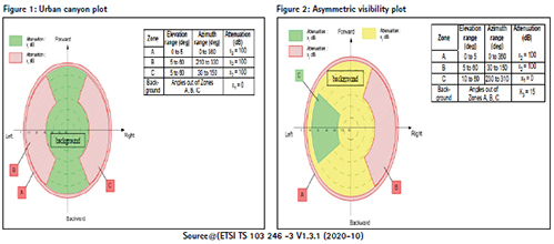
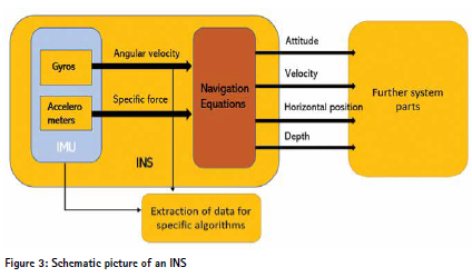
For this environment, different topics need to be considered. Typically, in settled regions, probability for interferences due to man-made RF-signal sources, as well as for multipath due to signal reflection on buildings is generally higher. Denser region is settled, greater probability. Worst cohesion this environment can be found in traditional highly populated urban area (e.g., Frankfurt, New York). Additionally, satellite view in this environment is obstructed on a low till extreme level due to man-made buildings which can also be based on structure and design generated multipath effects for example. In ETSI TS 103 246 -3 V1.3.1 (2020-10) some examples of sky attenuation conditions are described which can be used to simulate this environment. Focus should lie on described urban canyon (Figure 1) and asymmetric visibility plot (Figure 2).
Effects for interference and multipath are addressed in sections Multipath and Interference. Due to reduced visibility of satellites and reduced signal strength like described in Figure 1 and Figure 2 an increased measurement notehead be expected, which results in reduced accuracy, i.e., higher standard deviation. In serious cases a non-availability of GNSS-based positioning is possible.
▪ Mountain and valleys This environment usually has a lower probability for interference sources, but multipath effects still are common. As for settled regions, limitations in terms of satellite visibility are considerable but on or hand also heavily dependent on specific topographic features of analyzed area (e.g., position of higher mountains). Biggest issue can be found directly on mountain flanks and in valleys. effect intensifies as terrain gets steeper.
Satellite view can be generally described like in ETSI TS 103 246 -3 V1.3.1 (2020-10) due to similarities to settled region on this topic. Thus, sky attenuation conditions described in Figure 1 and Figure 2 can be used for critical environments. Due to these similarities, effects also resemble, and thus an increased measurement noise can be expected, which results in reduced accuracy, i.e., higher standard deviation. In serious cases a non-availability of GNSS-based positioning is possible..
▪ Different types of tunnels This group contains besides “traditional” tunnel environment, thus a “complete” obscuration of general RF-environment and sky, also tunnel gallery and or more complex tunnels like environments with open elements in tunnel wall. This environment type usually does not describe an environment for a complete these cases but more as a segment of available environment. This applies also to simulations. An example for this can be found in European eCall regulation for automotive sector (DR 207/79) wherein Annex VI 2.2.4 a test with a temporal absence of GNSS signals to cover tunnels is described.
General in these environments GNSS-based positioning systems cannot calculate a valid position solution (non-availability) because no satellite signals are available. With open elements in tunnel wall, for example in galleries, a possibility of reception of single satellite signals are possible. these signals can be used by certain positioning systems to support already trained sensor fusionbased positioning via advanced algorithms, but do not enable GNSS only positioning.
Multipath can be heavily expected at entrances of tunnels, but during passage, through tunnel, it can be considered irrelevant (since reliable GNSS signals will not be trackable anyway). This changes up to a certain level with open elements in tunnel wall, but due to size, they still can be ignored. Topics regarding interference within tunnels are limited to interferences based on installed equipment from tunnel operator and usually can be found in area of unintentional interference due to damaged or misused equipment. Topic of GNSS repeaters or related techniques (pseudofiles, synthetic extension, etc.) needs to be addressed. Background is these techniques are getting more and more common. these techniques try to enable reception of GNSS signals in these nonavailable or reduced environments and thus transforming at least up to a certain level into open environments (see ETSI TS 103 246 -3 V1.3.1 (2020-10), FigureA.1).
3.3 Integrity
Integrity is an important cornerstone of satellite navigation and an aspect of reliability focused on correctness of output. Integrity is assurance that all functions of a system perform within operational limits. It is measure of trust that can be placed in solution provided by railway positioning system. Role of integrity is to provide timely warnings to railway domain users when some system anomaly results in unacceptable navigation accuracy [1]. As for autonomous driving, a key parameter for railway domain is integrity of position solution to provide some safe and real-time KPI such as:
▪ Position protection level (horizontal/vertical): Protection level (PL) is a value that bounds error of position or velocity components provided by positioning terminal [2] with a very high probability and an estimate of maximum error in associated position output. Position output is misleading if true error is greater than protection level. Protection level is a common quality metric for high integrity positioning systems. Protection levels may be provided for individual position vector elements (e.g., latitude) or combinations (e.g., horizontal). Protection level is a real-time and dynamic quantity that is valid for each measurement epoch.
▪ Alert Limit (horizontal/vertical): maximum position error that automated driving application in railway domain can tolerate and still deliver its function. If protection level is greater than alert limit, error cannot be guaranteed to be within tolerable level and thus position solution should not be used by automated driving application in railway domain.
▪ Tolerable Hazard Rate (THR) Level: defined as occurrence rate vehicle control systems fails to stop vehicle at desired location, or its speed exceeds prescribed value, is used to quantify safety requirements. In railway systems, [3] an overall THR better than 10-9/h or even 10- 10/h is mandatory, and this can be attained only through a crosscheck with a GNSS-independent
Protection level and its associated Integrity risk, in terms of reliability (verification of risk) but also its efficiency and usability (size of Protection level, which is directly related to their usability for intended application). Users have to be informed with timely warnings in this accuracy of service is not sufficient for intended operation. In this case, user is safe.
3.4 Sensor-Fusion solutions
As already indicated in last section, GNSS-alone positioning lacks requested accuracy and continuous availability in challenging environments. In these cases, satellite-independent systems are necessary to complement and ensure a continuous positioning solution of required quality. Most prominent sensors to complement GNSS in railway domain are Inertial Navigation Systems (INS), which shall be introduced shortly in Section 2.4.1.
Moreover, specialized mathematical methods are needed to combine measurements of these two (or multiple) sensors. This is necessary since GNSS and INS systems do not measure same physical quantities and thus observations from both sensors must be combined on a common mathematical level (called navigation equations). Process of finding optimal combination between different sensors is referred to as sensor fusion.
Therefore, appropriate mathematical algorithms have to be utilized, which can account for strengths and weaknesses of observed sensor data (in terms of stochastic information). Most common technique for this task in navigation applications is Kalman Filter, which we introduce in Section 2.5.
3.5 Inertial Navigation Systems (INS)
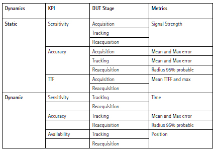
INS is a form of a dead reckoning navigation system that provides information about position, velocity, acceleration, and orientation using measurements taken from inertial sensors. It can be used as an autonomous system for navigation or is combined with complementary measurement systems (e.g., GNSS). Technically an INS represents combination of an IMU (Inertial Measurement Unit) and a computer running navigation equations using data collected by IMU. Later consist of sensors measuring angular velocities (gyros) and accelerations (accelerometers).
INS systems integrate rotation rates to obtain orientation changes and double integrate accelerations to obtain velocity and position increments. therefore, a relative orientation can be provided. Basic structure of an INS is visualized in Figure 1. Like every or measurement system, INS suffers from random and systematic errors. Due to errors in gyros, accelerometers, and with a mathematical background, an INS will have a drift in velocity, position, and attitude. To limit drift, an INS is usually aided by or sensors that provide direct measurements of integrated quantities. Any vehicle with an IMU and some aiding sensors can these aided INS to find its position, orientation, and velocity.
3.6 Kalman filter fusion algorithm
Most prominent technique for sensor fusion in navigation applications is Kalman Filter. Therefore, some basic information on technique is provided in following. In a mathematical sense, Kalman Filter represents optimal parameter estimator regarding Minimum Mean Square Error Estimator (MMSE) criterium. This holds for linear systems with measurement errors following a Gaussian distribution. Estimations are based on a statistically optimal combination of real measurement data and statistical quality information (a-priori noise estimations, covariance-matrices, etc.) In algorithm, observations of different sensors can be introduced and combined at different levels of processing. In general, two different approaches can be distinguished:
▪ Tightly coupled
Tight coupling approach follows mathematics of a centralized filter which is realized through a combination at sensor level, i.e., at level of raw GNSS observations, not at level of actual parameters estimated (e.g., position). Therefore, it is possible to not only estimate positions/velocities in Kalman Filter but already raw GNSS observations (e.g., pseudo-range).
▪ Loosely coupled
Loosely coupled process represents most common approach for GNSS/INS coupling. Combination of measurements is realized at level of actual parameters to be estimated (positions/velocities/ direction). Although this approach is easier to implement, it is also more prone to errors in actual raw data (pseudo-range, phase measurements, angular velocities, accelerations).
4. Assessment of GNSSbased systems
4.1 Key Performance Indicators
Key role of navigation within railway environment is to provide absolute positioning. Therefore, most Key Performance Indicators (KPI’s) should be identified to measure performance of components and processes. For train Localization, performance of GNSS system delivering position is critical along with additional sensors.
4.2 GNSS related performances
Performance requirements are generally stated as requirements on outputs of a given system component, assuming that or components feeding it with input information do respect their performance requirements. [2] standard for assessing GNSS performance in context of Train transport systems is not ready currently. Therefore, existing standards which are initially defined for or domains which provide identification and definitions of positioning performance features and metrics can be adapted accordingly.
▪ Position: is location of positioning terminal (or, more specifically, of some reference point attached to it, such as antenna phase centre) expressed in some specified reference frame (e.g., WGS84) and system of coordinates (e.g., geodetic or Cartesian). Position output can include all position components (e.g., longitude, latitude, and height) or just a subset of m (e.g., longitude and latitude) depending on needs of application.
▪ Velocity: is velocity of positioning terminal relative to ground. In its more general form, it is a threecomponent vector which will most typically be expressed in a Cartesian coordinate system whose frame is centered at user position (e.g., local horizontal reference frame, with coordinates referring to North, East, and Up directions).
▪ Speed: is norm of velocity vector, and hence describes how fast user moves (relative to ground) irrespective of direction. It is of relevance in many applications and hence it shall be specifically addressed. When accompanied by heading, speed provides an equivalent description of velocity vector of a vehicle (provided that its motion is mainly horizontal, which is typically case with land vehicles). Depending on specific application, it can be convenient to present motion information to user in form of speed and heading, but in general, velocity vector is most informative.
▪ Accuracy: it depends on several factors (e.g., satellite visibility, constellation geometry (characterized by Dilution of Precision (DOP)), un-modelled ionospheric and tropospheric errors, multipath, jamming,).
▪ Availability: despite global coverage of navigation systems, it is not always possible to obtain position, also due to some physical obstacles that limit satellite visibility.
4.3 Performance metrics
Performance metrics are precise definition of means of measuring a given performance feature of a given output of a system. This section defines positioning metrics related to position, velocity, and speed from existing standards.
1. According to CEN/EN 16803-1 [1] identification of performance features and definition of metrics are as follows:
▪ provides identification and definitions of positioning performance features and metrics that characterize GNSS Based Positioning Terminals (GBPT) performance requirements.
▪ these have to match a certain operational scenario, i.e., conditions in which GBPT is operating that may have a huge impact on its performances.
▪ accuracy associated to position error, velocity error, or speed error,
▪ integrity determined by protection level given an associated integrity risk.
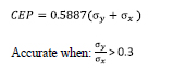
2. According to ETSI TS 103 246-3, [2] standard defines three position horizontal accuracy and vertical accuracies performances for a moving vehicle in an open sky condition for urban canyon and asymmetric sky view scenarios requirements classes Performances for horizontal. Assessment of GNSS for train applications are based upon device under test. Appropriate metrics to quantitatively characterize KPIs have to be extracted from device under test used.
However, identified KPI must be measured also under two DUT dynamics: static and dynamic, at three signal-processing stages (states) of DUT: acquisition, tracking and reacquisition. Following table defines dynamics, associated KPI and metrics.
4.4 Assessment Methods
Under a statistical perspective, as means to assess above-mentioned KPIs with proper metrics extracted from receiver observables, following methods can be used. This section summarizes following three methods [5] used to provide a measure of system performance in navigation. These methods are appropriately used to compute performance metrics from receiver observables when accuracy is considered. Below accuracy metrics overall represent a measure of average positioning error with a certain percentage of confidence. Assuming Gaussian-distributed errors, direct conversion is possible among abovedefined metrics.
• Circular Error Probable (CEP)
Circular Error Probable (CEP) is radius of circle that encloses 50 percent of probability of a hit in two dimensions, i.e., if a CEP of 5meters is quoted n 50% of horizontal point positions should be within 5 metres of true position. Several methods are possible for computing CEP. This CEP is an integral of bivariate (twovariable) Gaussian probability function in a plane. radius of 95% with radius of 95% probability circle and it is computed as:
Radius of circle centered at true position, containing position estimate with probability of 50 %. parameters σy and σx are standard deviations of error along two perpendicular axes in a plane, and 0.5887 is a dimensionless constant was derived using a 50-percent CEP in integration of a bivariate Gaussian probability distribution x s y s
• Height Error Probable (HEP) HEP can be calculated to determine an altitude error independent of CEP and SEP. SEP combines both horizontal and vertical errors. Since vertical error is generally greater than horizontal error, SEP will be influenced dominantly by vertical error; therefore, by computing HEP, CEP, and SEP, one can better determine distribution of errors.
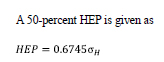
derivation of this equation assumes a Gaussian probability function in vertical direction. parameter is standard deviation of error in height.
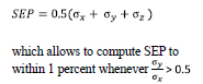
• Spherical Error Probable (SEP)
Above result can be extended to threedimensional (3D) case: SEP. SEP is an integral of tri-variate (three-variable) Gaussian probability density function over a sphere, which is centred at mean. Two equations were found to compute 50-percent SEP. most common is:
CEP, HEP, SEP, state nothing about quality or accuracy of data used in computing location of a target. these items are a measure of dispersion and of central tendency.
5. Conclusion
Under consideration of current approval processes in railway environment based on standards like EN 501026 RAMS-process (reliability, availability, maintainability, and safety) and available GNSS standards like EN 16803-1 and ETSI TS 103 246-3, the described approach presents a possible high-level process for assessment of GNSS bases systems. Sensor fusion is key for improvement of integrity and is assessed in more detail in the project CLUG. This together with other research activities of NavCert may lead to more specific standardization and regulation for smoother implementation of ERTMS L3.


 (No Ratings Yet)


Leave your response!