| Applications | |
Tracking ship using INSAT
In this paper the topics of INSAT coverage, INSAT-MSS modem architecture, working principle,RTOS-based data logger, data reception software and commissioning are detailed |
 |
|
 |
|
The most basic operation of a vessel monitoring system is to determine the location of the vessel at a given time, and periodically send this information, usually by satellite, to a monitoring station ashore. Most of vessels are tracked using the purple finder. This finder uses various satellites like Inmarsat, Globalstar and Thuraya for tracking the vessel. INMARSAT-C has been the most considered choice, since INMARSAT transceiver is already fitted onboard many ocean-going vessels as required by GMDSS (Global Maritime Distress and safety System).
The carriage and operation of VHFbased Automatic Identification System (AIS) onboard vessels, as required by the revised SOLAS (Safety of Life at Sea) international convention, has greatly improved the identification and tracking of vessels in coastal waters. However, it needs to be extended in coverage, at least over the entire EEZ (Exclusive Economic Zone). It is also adopted as an Automatic Location Communicator (ALC) in the VMS (Vessel Monitoring System) of many regional fishery management organizations (RFMOs) and countries. Implementation of the long-range mode of AIS with INSAT- 3C satellite communication and the multipurpose performance of such a system is discussed in the paper.
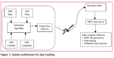
The designed ship track system as shown in figure 1 is installed in NIOT research vessel. Data logger collects the date, time and positional details (Latitude, Longitude) from the in-built GPS transmits, and transmits the GPS details through INSAT-MSS modem using serial (RS232) port. Reception hub receives the data from MSS transponder on INSAT-3C satellite. The hub sends the data to NIOT mail server. Data reception software running on server checks the mail server continuously and shows the exact ship location, generates *.kml (Keyhole Markup Language) file depending on the period selected, calculates the average ship speed and generates a back up of the data in database for future use.
System architecture
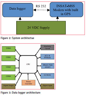
System contains Data logger, INSAT-MSS modem with in-built GPS, 24 volts DC supply as shown in the figure 2. RS-232 is used for data logger to communicate with INSAT-MSS modem. Data logger gets the GPS data from the inbuilt GPS available in INSAT MSS modem and stores it in the memory. Depending on the slot assigned data logger transmits the data through INSAT-MSS modem.
Data logger, a Single Board Computer (SBC), is an expandable embedded controller designed for industry applications to replace PC or PLC devices in harsh environments. It supports Input/ Output (I/O) expansion bus that is used to implement various I/O functions as shown in figure 3. The salient features of data logger are Digital input/output channels, Analog/Digital channels, 4 serial ports, 2 no’s of RS-485 port of 3000V isolation, Real Time Clock (RTC), Non-Volatile Random Access Memory (NVRAM), Static Random Access Memory (SRAM), Flash memory, Electrically Erasable Programmable Read Only Memory (EEPROM) and Watchdog circuit. Data logger has 64-bit internal hardware serial number, 1 LED (Light Emitting Diode) display used for power or communication indicator, 5 digit 7 segment LED display and I/O buffer. Data logger supports 10 types of I/O Expansion Board used to expand the features of the controller. Depending on the type of embedded firmware programs and I/O Expansion Board, the data logger is used as a single versatile controller. Data logger uses Mini RTOS (Real Time Operating System). The Mini RTOS is a set of commands or code that manages the computer how to process information. RTOS runs programs, manages files, controls information processing, directs input and output, and performs many other related functions. The memory details of the data logger are 512 K bytes SRAM, 512 K bytes Flash, 2 K bytes EEPROM, 31 bytes NVRAM. The nominal working voltage is non-regulated 10 to 30 volts (DC) at 3 watts power consumption. The operating climatic conditions are -25°C to 75°C, (0 to 90) % humidity
INSAT details
Depending on the frequency of operation, INSAT modems are of 2 types, namely INSAT-DRT and INSAT-MSS.
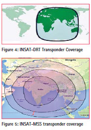
INSAT-DRT:- INSAT-DRT (Data Relay Transponder) works in UHF (Ultra High Frequency) band (402 MHz). INSAT-DRT modem transmits from remote location to satellite and from satellite to the reception hub in C- band. Received data is processed in data reception server for data quality. It is extensively used in land-based AWS (Automatic Weather Station), ship-based AWS, tide gauge network, MET-Ocean Buoys and other observation platforms by IMD (Indian Meteorological Department), INCOIS (Indian National Centre for Ocean Information Services), NIOT (National Institute of Ocean Technology) and ISRO (Indian Space Research Organisation). It supports a transmission rate of 300 bps (Bits per Second). INSAT-DRT transponder has coverage in Africa, Asia and Australia continental mainland and ocean area also as shown in figure 4.
INSAT-MSS:- INSAT-Mobile Satellite Services works in S-band (2.6 GHz). Modem transmits the data to the satellite and the same is been received in hub in C-band. INSAT-MSS has a less coverage compared to INSAT-DRT as shown in figure 5.
INSAT-3C satellite has a wide coverage of India mainland, Bay of Bengal, Arabian Sea and Indian Ocean. The modem used in this paper works in inner lobe area only covering Indian mainland, Bay of Bengal and Arabian Sea due to a small antenna dish and less transmission power apt for scientific applications. Antenna size and power consumption should be minimal for easy installation, maintenance and longer system life in remote locations.
Both modems work in TDMA (Time Division Multiple Access) mode. In this paper, INSAT-MSS modem is used for ship tracking. In the next section, INSATMSS modem architecture, the reporting network has been explained in detail.
The details of INSAT-based modem are explained in detail in following section.
INSAT MSS modem architecture
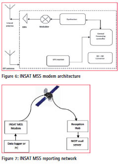
The INSAT-MSS terminal uses SXC transponder of Indian geostationary satellite INSAT-3C. The INSAT-MSS terminal mainly consists of S-band synthesizer, BPSK modulator and SSPA, GPS receiver, Central processing controller, DC-DC converter, S-band and C-band antennas[1] as shown in figure 6.
Central Processing Controller (CPC) controls the modem hardware and GPS receiver data. The DC to DC converters keeps the output voltage level (9–36VDC) to the required voltage level irrespective of the load. The GPS receiver is used to collect date, time, latitude and longitude and stores in to CPC. Binary Phase Shift Keying (BPSK) is digital modulator scheme that conveys the data by changing or modulating the phase of reference carrier signal. The Synthesizer generates required range of frequencies from a single fixed oscillator to lock the frequency to transmit the data.
The analog part of INSAT modem has been designed with Solid State Power Amplifier (SSPA) which takes advantage of current cutting edge technologies in both design and manufacturing, thereby resulting in high reliability, high performance and cost effective alternative to the Traveling Wave Tube (TWT).
All these sub-systems are housed in an IP65 enclosure suitable for marine conditions. The power supply and interface connector are located outside of the terminal. Users can configure terminal ID, frequency of operation by using RS-232 interface. MSS terminal operates in TDMA (Time Division Multiple Access) mode which has unique ID code operated in S-band and transmits messages at 300bps. The INSAT MSS modem works in S-band at a frequency of 2.6 GHz with down-link in a C-band.
INSAT-MSS reporting network
Data logger sends the data through RS-232 to INSAT-MSS modem for transmission which is received by the INSAT-3C satellite. The Reception hub receives the data from satellite and sends it to NIOT mail server immediately without delay as is shown in figure 7.
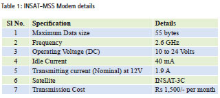
INSAT-MSS modem details
A control string ‘@#N’ is required at the start of data to transmit and avoid false triggering. To receive the latitude, longitude, date and time from the built-in GPS, the command is ‘@#G’. The power consumption during idle mode of INSATMSS modem is 40mA. The idle mode current of satellite modem contributes a major part in the power budget while sizing the communication system, as this modem is idle for most of the time and transmission takes only a few seconds with peak current. The details of INSAT-MSS power consumption and cost are shown in table 1 which also indicates that INSATMSS is economical compared to Iridium, which needs about Rs 40,000/month.
In-built GPS details
INSAT–MSS modem has an inbuilt GPS receiver. It supports NMEA (National Marine Electronics Association) format. The modem takes a minimum time of 45 seconds to acquire the GPS and send the same to data logger. GPS data contains date, time, latitude, longitude details at that particular time.
Program architecture
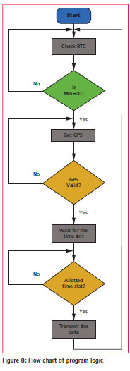
Data logger checks its RTC (Real Time Clock) time continuously for 0th minute of every hour to send GPS request to INSAT-MSS modem. Data logger checks if the received GPS data is valid or not. If the GPS data is invalid then data logger sends the GPS request for a maximum of 3 times. GPS data is stored in temporary memory. Data logger waits for the allocated transmission slot, since the modem is used in TDMA mode. When the RTC is exactly the same as the time slot allotted for the particular ship, data logger transmits the latitude, longitude, date and time through INSATMSS modem. Data logger runs in infinite loop as shown in figure 8.
Data reception software
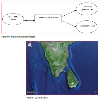
Data reception software runs continuously on server computer. It receives the data from the NIOT server, decodes it and generates the .kml file showing the ship track as shown in figure 9. The software features are to calculate the distance traveled for the particular selected period, GPS data backup for future reference, continuous ship tracking, etc. In future, the software can be upgraded to calculate the average speed, Expected Time of Arrival, sending Vessel position reports through SMS, E-mail, etc.
Commissioning of Track ship system
Track ship setup was installed on Coastal Research Vessel Sagar Purvi in Chennai, India. INSAT-MSS modem was installed on the top most location in the ship. The data logger inside the ship was powered with 24 volts uninterrupted power supply. The vessel being tracked sailed from Chennai to Kavaratti Island (Lakshadweep) via Tuticorin, Kollam. The same has been shown in Bhuvan (Gateway to Indian Earth Observation), an Indian Geo-portal in figure 10. Bhuvan is a software application which allows the exploration of a 2D/3D representation of the Earth’s surface. The browser is specifically tailored to view India, offering the highest resolution in this region provided with local four languages. Apart from visualization, Bhuvan provides timely disaster support services, free satellite data and products download facility and rich thematic data-sets. Bhuvan is using crowdsourcing approach to enrich its maps and collecting Point of Interest data.
Conclusion
The tracking of ships using Indian satellite has been successfully implemented, tested and commissioned. The positional information has been exported to an Indian Geoportal, Bhuvan. The system can be used for better tracking in Indian waters using domestic satellite. Commercial decisionmaking, fleet management and cost control can be improved by using the tracking system. Presently, only one industry provides ship tracking services using various satellites. The developed system is very cost-effective compared to the commercially available vessel tracking services. Ships can be tracked in the vast Indian Ocean region if INSAT-DRT modem is used, since the INSAT-DRT satellite footprint is large.
Acknowledgement
Authors gratefully thank Dr. M.A.Atmanand, Director, National Institute of Ocean Technology Chennai, for vital encouragement and support for this development work. Also the authors wish to thank Vessel Management Cell (VMC), NIOT for installing the track ship system in vessel and all team members of Ocean Electronics Group, NIOT
Reference
[1] Muthukumaravel.S, Tata Sudhakar, Chiranjeevi Vivek.G, Atmanand.M.A,“Low power satellite Communication for ocean observation”: Proceedings of ICCCI 2013, International Conference on Computer Communication and Informatics.
[2] Chang, S.J, “Satellite-based vessel tracking and monitoring as the long range mode of AIS”: OCEANS, 2005. Proceedings of MTS/IEEE
[3] Xiu-fang Cui, “Research on vessel monitoring system”: 2nd International Conference on Mechanical and Electronics Engineering (ICMEE), 2010
[4] Wangqiang Niu, “The Integrated Ship Monitoring Systems: from Small Size to Large Size”: International Workshop on Intelligent Systems and Applications, 2009
[5] Reynolds, J.C, “GPS-based vessel position monitoring and display system”: Position Location and Navigation Symposium, 1990. The 1990’s – A Decade of Excellence in the Navigation Sciences, IEEE PLANS ‘90
[6] Bhuvan Website, http://bhuvan. nrsc.gov.in/bhuvan_links.php


 (1 votes, average: 4.00 out of 5)


Leave your response!