| Positioning | |
Track me if you can!
The specialized positioning system used for the tiny insects, such as bees, has been proposed in this article |
|
 |
|
||||
 |
|
||||
 |
|
||||
 |
|
||||
This paper is going to provide a concept of a new system for positioning the target bees. The biologists eagerly wish to collect the bodies of the bees in order to find the causes of the colony collapse disorder (CCD) of bees. As we know it, there are several ways used to find out and trace animals. For example, the scientists set up the transponders or the GPS trackers on the top of shells of thalassians or on the feet of migrant birds by ringing. These methods make great contributions for tracking and studying in the field of the biological research. However, how to track or position small insects, like cicadas, butterflies, or bees, is still a problem needed to be solved. The obvious crux of the problem is the size and the weight of the devices which are not suitable for fitting on such a small insects.
It seems impossible to get the radar reflection signal from such a tiny target, since the surface of the target is too small. The most instinctive solution is to design a transponder which is able to reflect signals. Since the transponders need to be set up on the target insects, the size and the weight of the transponders are strictly limited. In order to achieve the requirements of the transponders, setting the operation frequency up to gigahertz may provide the possibility to creating such a small transponder.
In the article of Riley and Smith [1], a harmonic radar system was proposed to investigate the flight insects at low altitude. This harmonic radar system is used to record the flight trajectories of low-flying insects over ranges of hundreds of meters. In this system, the light weight transponders which are able to double the carrier frequency through a passive diode without the aid of on-board battery are used to fit on the insects. Because of the non-linear electrical conductivity, the diode generates a current which containes harmonic frequencies of the original carrier signal. By detecting the second harmonic signals reflecting from the transponders, the system can measure the transmission delay and get the position of the target insect.
In the previous paragraph, the harmonic radar system proposed by Riley and Smith is suitable to track the flight area of the target insects at low altitude over ranges of hundreds of meters. However, it is not suitable for positioning the target insects in the requirement of high precision since the limitation of the range resolution. According to the system structures of the harmonic pulse radar, the best resolution is about 20 m. To find a small insect in the range on 20 m by human vision is a very tough challenge. Therefore, it is necessary to develop a system with high accuracy in measuring the ranges of target tiny insects, such as bees.
The positioning system proposed in our paper is going to provide a possible solution for achieving the requirement of high resolution in measuring the range. The systems used to positioning or tracking the tiny insects usually have to face the problems of weak signal reflected from the targets. The most straight forward method to overcome this problem is to increase the output power of the radar. However, it is only increase the search distance but not the resolution. The similar situation of weak signal exists in the global positioning system (GPS) [2]. The signals of GPS travel 20,000 km distance from the satellites to the earth’s surface, causing -157dB path loss. The signal received by the users on the earth’s surface is usually very weak. The spread spectrum technology is used to overcome the weak signal problem. This technology also inspires us to use the similar methodology while dealing with the similar weak signal situation for positioning the tiny insects.
In our system, a modified-BPSK modulation is adopted to overcome the problems of weak signal and the non-linear frequency doubler. A high sampling rate over to gigahertz is used to increase the range resolution. With the increase of the sample points, the curse of dimensionality happens while computing the autocorrelation values with different delays between the transmitted (Tx) and the received (Rx) signals. The reasonable improvements of algorithm will be provided to reduce the computation time.
The details of our system will be provided in the following sections. The basic positioning method will be discussed in Section 2. The modified-BPSD modulation will be illustrated in Section 3. In Section 4, the high sampling rate for the high ranging resolution will be mentioned and discussed how to deal with the related huge numbers of simple points. Some indoor experimental results will be provided in Section 5. At the end of this article, the possible improvements and future works will be discussed.
Positioning method
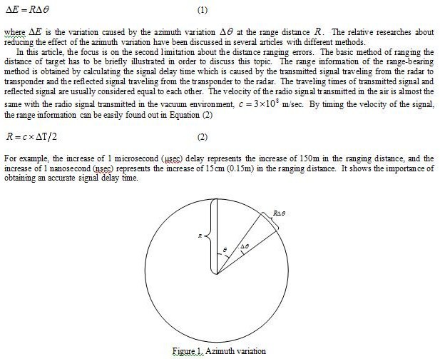
In order to get the positions of the target insects, the range-bearing method is adopted. This positioning strategy is widely used in military radar systems and relative radar systems for tracking or positioning insects [1], [3]. The system can provide the information of the azimuths and the ranges of the target insects. However, there are some known limitations of the system needed to overcome. The first limitation is the accuracy of the azimuth. While the reflected signal is detected, the azimuth information can be obtained through the rotation servo system. The resolution provided by the rotation servo directly affects the accuracy of the azimuth. In addition to the effect of the rotation servo, the beam width of the antenna is also the major factor which causes the accuracy variation of the azimuth. No matter which factor causes the inaccuracy of the azimuth, the variation of 1 degree in the azimuth information cause about 1.75m variation at the 100m range distance. This relation can be expressed as Equation (1) and shows in Figure 1.
The pulse radar system is widely used in the field of military and in the some insects tracking system [1]. After transmitting the trigger pulse, the radar system provides the ability to measure the signal delay though a signal power detector and a serial-to-parallel register. However, the hardware structure of the pulse radar system limits the measurement accuracy of the delay time. Therefore, a part of the methods proposed in this article is to increase the sampling rate of the analog to digital convertor (ADC) in order to give the higher accuracy of the delay time. The relative issues will be mentioned in Section 4.
Modified-BPSK modulation
As mentioned in the introduction, the systems used to positioning or tracking the tiny insects usually have to face the problems of weak signal reflected from the targets. The similar strategies used in GPS to deal with the weak signal problem are also adopted in our system. There are two major methods of the original GPS design which are adopted in the proposed harmonic radar system. The first one is the pseudo-random-noise (PRN) code which is applied to provide the ability of the code division multiple access (CDMA) [4] which allows several users to share a single bandwidth. Here, the autocorrelation properties of PRN code are used to measure the delay between the transmitted signal and the received signal. The operation is similar to the acquisition operation on the GPS receivers. The details of autocorrelation will be illustrated in the next section.
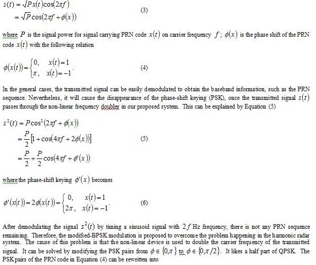
The binary phase-shift keying (BPSK) modulation is the second major method adopted here. In our application, there is only PRN code need to be modulated onto the carrier but the navigation information. For the most part of communication systems using the BPSK modulation, the transmitted signal can be formulated as Equation (3)
High ranging resolution
In order to improve the ranging accuracy of the harmonic radar system, the spread spectrum techniques are adopted in our system. The autocorrelation properties of the PRN code make the alignment between the transmitted signal and the received much more precisely. Besides the good properties of the autocorrelation, the high sampling rate is also a crucial factor to increate the accuracy of the delay time between the Tx signal and the Rx signal. For instance, the 10 MHz sampling frequency provides the accuracy of 100 nsec, which means the 15m ranging resolution. And the 1 GHz sampling frequency provides the accuracy of 1 nsec, which means the 15cm ranging resolution. Nevertheless, there is no free lunch while pursuing the accuracy performance. The higher sampling rate provides the higher ranging resolution and also gets much more data needed to deal with in searching the maximum value of the autocorrelation value. Therefore, there are two methods in the following two subsections.
Floating point operation reduction
Before discussing the floating point operation reduction, the calculation of the basic autocorrelation between the Rx and Tx signals have to be reviewed in the following formulations.
without sacrificing the accuracy of the autocorrelation value obtained in Equation (7).
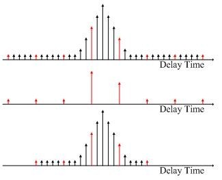
Figure 2. Sub-Sampling reduction
Sub-sampling reduction
Although a huge numbers of floating point operation have be avoided in the last sub-section, it still needs a lot of computation time spending on searching the maximum autocorrelation value with different delay between the Tx and Rx signals. Once the sampling frequency rises to certain level, the huge number of sampling points will make it difficult to do a full search on every sampling point. Nevertheless, the strategy used in the GPS acquisition loop shows that only 16 sampling points on each chip are enough to search the meaningful maximum autocorrelation value. Although the obtained delay corresponding to the maximum autocorrelation value is quite inaccurate, it provides the help of reducing the search range in the different delays. After finding the rough delay, it only needs to search the nearby range of the rough delay as showing in Figure 2.
Experiment results
The focus of the experiments is on verifying the ideals of the modified-BPSK combining with the harmonic radar system and the strategies to deal with a huge number of sampling points. In order to verify the proposed ideals quickly, the carrier frequency is chosen at 2 GHz frequency. The relative devices of 2 GHz can be manufactured by the printed circuit board (PCB) techniques in the lab. The FPGA board manufactured by Xilinx is used to generated the PRN code with almost the same specifications with the coarse/acquisition (C/A) code used in the GPS as listed in Table 1.
The sampling rate of the ADC is set to 2 giga-samples per second (GSa/s) by using the oscilloscope manufactured by Agilent to capture 4 million sample points simultaneously from the Tx signal before modulating and the Rx singal after demodulating.
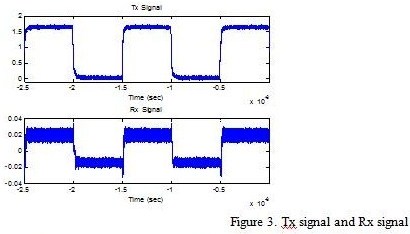
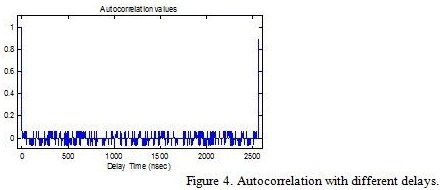
In Figure 3, it shows that the modified-BPSK modulation is successfully implemented in the harmonic radar system. The baseband signal can be retrieved from the second harmonic carrier signal in 4 GHz frequency. By using the algorithms illustrated in the previous section, the maximum autocorrelation value between the Rx and Tx signals with different delays can be found out in 1 second and the respective results are shown in Figure 4.
Conclusions
The specialized positioning system used for the tiny insects, such as bees, has been proposed in this article. In order to achieve the purpose of positioning the target accurately instead of only tracking the target in a rough area, the ranging techniques of the pulse radar system are improved by using the spread spectrum technology which is inspired from the GPS and the other communication system. The autocorrelation properties of the PRN code help us to overcome the weak signal problems and increase the ranging accuracy. The modified-BPSK modulation makes the spread spectrum technology become possible to combine with the harmonic radar system. The two algorithm strategies are proposed to reduce the computation time while searching the maximum autocorrelation value between the Rx and Tx signals with different delays in a high sample rate which is used to increase the ranging resolution. According to the experiment results, the ranging accuracy of the proposed harmonic radar system is indeed in the range of 1m.
The preliminary results of the ranging distance are much better than the original harmonic radar system. However, there are still a lot of problems needing to be considered such as the azimuth variation problem still needs to be overcome.
References
[1] Riley, J.R. and Smith, A.D.: Design Considerations for an Harmonic Radar to Investigate the Flight of Insects at Low Altitude, Computers and Electronics in Agriculture, 35 (2002), 151-169.
[2] Misra, P. and Enge, P.: Global Positioning System: Signals, Measurements, and Performance, Ganga-Jamuna Press, Lincoln, Mass, USA (2006), 2.
[3] Drake, V.A., Harman, I.T. and Wang, H.K.: Insect monitoring radar: stationary-beam operating mode, Computers and Electronics in Agriculture, 35 (2002), 111-137.
[4] Borre, K., Akos, D.M., Bertelsen, N., Rinder, P. and Jensen, S.H.: A Software-Defined GPS and Galileo Receiver: A Single-Frequency Approach, Birkhäuser, Boston, Mass, USA (2007).
My Coordinates |
EDITORIAL |
|
Mark your calendar |
August 2011 TO December 2011 |
|
News |
INDUSTRY | LBS | GPS | GIS | REMOTE SENSING | GALILEO UPDATE |






 (3 votes, average: 1.00 out of 5)



Leave your response!