| GNSS | |
GNSS threat quantification in the United Kingdom in 2015
This paper introduces a summary of the GEMNet system, and presents two sets of results. Firstly, characteristics of interferers observed operationally along with the impact that they caused on two types of operational GNSS receivers. Secondly the results are presented from laboratory tests where jamming “signatures” were played back to two type of GNSS receivers at substantially higher power |
 |
|
 |
|
 |
|
 |
|
 |
|
 |
|
Overview of Project GEMNet
Global Navigation Satellite Systems (GNSS) threats and vulnerabilities have received considerable exposure in open publications and in the press in recent years. Although a number of important studies have been undertaken, several significant gaps were identified in understanding the impact that illegal jammers and other interferers in the GNSS spectrum cause to GNSS users in operational situations. Project GEMNet was initiated as a collaborative activity jointly by the Satellite Applications Catapult and Ordnance Survey (OS) to further the state of knowledge and to begin to address these gaps. After initially assessing the state of knowledge in this field (not reproduced in this paper), the GEMNet operational monitor system was set up with the following core aims:
1. Monitor the GNSS radio spectrum at a number of UK locations in order to quantify the occurrence of jammers in operational environments;
2. Capture “RF signatures” of jammers (both to understand the characteristics of threats, and to support aim 4 below);
3. Assess the impact of jammers and other interference on operational GNSS receivers;
4. Assess the impact that closer or more powerful jammers could have on GNSS receivers, i.e. different operational environments;
GEMNet Sensor System (GEMSS) equipment was set up and deployed in operational situations typical of where Critical National Infrastructure (CNI) equipment is collocated.
This paper introduces a summary of the GEMNet system, and presents two sets of results. Firstly, characteristics of interferers observed operationally along with the impact that they caused on two types of operational GNSS receivers. Secondly the results are presented from laboratory tests where jamming “signatures” were played back to two type of GNSS receivers at substantially higher power.
GEMNet System
System Architecture
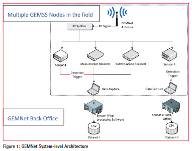
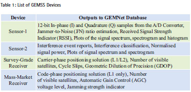
Figure 1 illustrates the GEMNet system architecture, which comprised a back office at the Satellite Applications Catapult, and a number of remotelydeployed GEMSS nodes. Each GEMSS Node incorporated multiple sensors and receivers to provide a detailed analysis on the nature and extend of GNSS interference in the vicinity of the Node. Table 1 lists sensors and receivers within a Node, and briefly explains the captured data from each element.
GEMSS utilised an active, Right-Hand Circular Polarised (RHCP) L1/L2 antenna. The radiation pattern for the antenna includes minimal attenuation at low elevations (close to the horizon) since this is the expected direction of arrival of the interference signals. The GEMSS antenna was connected to the sensors/receivers via an active RF splitter. The data from each sensor/receiver are stored locally and also available online through a secure link.
Deployments
Four different locations were used for GEMSS sensors. In all cases the antenna was roof-mounted nearby to existing operational GNSS antennas. The signal from the existing antennas was not taken for two reasons. Firstly, and most importantly, in order to avoid any disturbance to normal operation of those equipments. Secondly, the antennas themselves sometimes implemented technologies that mitigate interference. For example, choke ring antennas are designed to mitigate multipath, but they also attenuate interference emanating from sources at low elevations. Had choke ring antennas been used, the findings would have demonstrated the ability of choke rings to substantially attenuate signals at low elevations, and therefore potential interference sources would have been missed.
The GEMNet antennas were interconnected to the GEMSS platform via low-loss coaxial cable. The GEMSS platform was housed inside secure and weatherproof facilities, and were mains powered.
For this open version of the GEMNet report, locations are not described further since knowledge of their locations could alter the behaviour of those who commonly use GNSS jammers. Since one important element of the study was to assess the real operational situation, it was important to avoid this.
GEMNet Findings On Operational GNSS Interference
Datasets captured from the GEMNet sensors were analysed in detail and yielded over 1800 interference events with Sensor 1 over 100 observation days among four sites. Sensor 2 captured more than 600 interference events over more than 100 observation days among the same sites. The higher number of events with Sensor 1 reflected the higher sensitivity setting used for this device. Each GEMSS node captured a rich set of observables to support analysis of GNSS interference. The GEMNet database consists of two separate datasets. Dataset-1 comprised the raw data captured by three elements: Sensor-1, and the mass-market and survey-grade receivers. It was analysed using bespoke post-processing software developed in-house. Dataset-2 was provided by Nottingham Scientific Limited (NSL), the supplier of Sensor-2, after processing the raw data with their back-office.
Dataset-1 Summary
This section reports interference characteristics logged as Dataset-1. Table 2 provides a summary of Dataset-1 characteristics for the monitoring site designated Site 1. Data captured at other sites was analysed in the same way as for Site 1, and was found to have similar characteristics; due to space limitations it is not reproduced here.
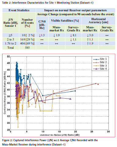
Events in the table are categorised into three groups with respect to their maximum power levels measured by Sensor 1. More than two thirds of observations (69%) were of less than 2dB J/N0, 29% were between 2 and 5 dB, and only 2% were above 5dB. As well as most interference being of low power, the majority of the captured interference were of very short duration (5s or less). The low power observed was consistent with low power vehicleborne PPD jammers that were the assumed source of interference, and the separation distance between the GEMSS antenna and the roadways on which vehicles were travelling.
The “impact on the receiver” section in the table illustrates the average change in some normally-available receiver output parameters (The tables with the symbol “↓” indicate a drop, with the symbol “↑” indicate a rise, with the symbol “↔” indicate no significant change in the particular receiver observable). The low interfering power led to minimal variations in receiver observables. With the survey receiver, no change in horizontal positioning accuracy performance was recorded. This same receiver saw an average 8% reduction of number of visible satellites during the 10 higher-power interference events, but this was not reflected in a worsening of position. The mass-market receiver recorded only a marginal reduction in number of visible satellites (1.9% during the 10 higher power jamming events). Horizontal accuracy with the mass market receiver was almost unaffected by the interference (average of 1.9 and 1.1 cm worse position for lower interference categories), and 3 cm improved horizontal positioning performance during the 10 higher interference power events. There is no physical mechanism in a normal GNSS receiver whereby increased interference power should improve positioning accuracy performance; rather the marginal improvement in these 10 cases is assumed to reflect typical variations in positioning performance when using small statistical samples.
Figure 2 plots interference power with respect to observed C/N0 output from the mass-market receiver, at four GEMSS monitoring stations. The variations in observed C/N0 continued to lie within its normal operational range despite the interference. As recorded in the table above, the positioning accuracy also remained within normal operational levels for both mass market and survey-grade receivers.
The vast majority of interference was of very low power and short duration, and caused no significant impact on GNSS receiver performance. The GEMNet sensor sites were between 50m and 200m from roadways (the assumed locale from which interference emanated). Interference at this range would typically be reduced by between 20 and 30 dB relative to the level expected very close to the interferers themselves. Closer separations between interferers and GNSS antenna, and/or higher power interferers, would change this observation and worsen the observed impact of interferers. Intelligent siting of GNSS antennas, or antenna or receiver mitigation technologies could counter the impact of higher interference powers.
Generally interference power was low, typically less than 5 dB jammer to noise ratio (J/N). A peak interference power of about 25 dB (J/N) was observed. This observation is consistent with a close approach (perhaps 10 m or less) of a low power jammer to a GEMNet GEMSS site. This observation might alternatively reflect the rare use of a substantially more powerful jammer, although a close low power jammer appears to have been the likely cause.
Dataset-2 Summary
This section reports interference events logged as Dataset-2 and coming from Sensor 2, the commercial interference detector. Table 3 provides a summary of Dataset-2 characteristics for the monitoring site designated Site 1. Figure 3 and Figure 4 provide ways of visualising certain details of interference characteristics, and are provided as an example of the several outputs from this dataset. At Site 1, 43% of events were of 15 seconds or longer duration. “Event Priority” is a parametric assessment of the importance of the observed events, with 88% of Site 1 events recorded as very low priority. Even the 8% of observed events designated as high priority events did not lead to substantive impact on the GNSS receivers, as reported in the previous section. The commercial detector was produced by Nottingham Scientific Ltd (NSL), and included a suite of functionality to process and categorise observed interference, although only a subset was used for the GEMNet work. A full library of event characteristics was captured, an example is shown in figure 4.
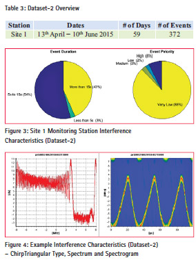
The interference characteristics captured by Sensor 2 aligned with the ones captured by the in-house developed Sensor 1, although for research purposes Sensor 1 had been set to be somewhat more sensitive and consequently captured more lowpowered interference events. As with Sensor 1, Sensor 2 showed clearly that most events were of low interfering power and had short duration.
Impact of Higher Power Interference on GNSS Receivers
Test Configuration
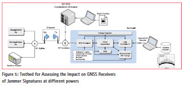
Operational field measurements showed that many interferers were detected at all GEMNet sites, but that interference powers were of such low power that GNSS receivers were largely unaffected. There are many situations where interference sources (e.g. jammers) could come closer to CNI sites than occurred during the GEMNet trials. This would cause a higher interference power at the CNI GNSS receiver than the powers observed. This approach also addresses the possibility that future jammers might be more powerful than today’s. In order to assess the impact of higher levels of interference on GNSS receivers, a non-radiated RF experiment was devised, as illustrated in Figure 5. Two receivers were used for the test:
1) A mass-market receiver (calculates position based on code phase measurements);
2) A survey-grade receiver (calculates position based on carrier phase measurements).
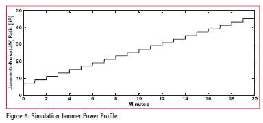
The receivers under test were provided with a simulated GPS signal using a Spirent GSS-8000 GNSS constellation simulator and a reconstituted interference signal. The interference was created using a software-defined radio from the captured I and Q measurement samples of interference from the Sensor 1 database. The captured digital signature was up-converted and “played back” in a loop at the GPS centre frequency. The power level of the played back RF interference signatures could be adjusted to observe the impact of higher jamming power levels on GNSS receivers under test. Figure 6 shows how the power level was varied during the tests.
The satellite simulation was set up and run without any interference. Once the receiver was tracking the simulator signals and calculating positioning satisfactorily, the amplitude of the interference was slowly increased to, and then beyond, the point where the receiver began to lose tracking capability. During the test, position and other observables were logged from the target receiver once per second. From these results it was possible to assess the margin of reliable operation (in dB) with respect to the original incident jammer. This effectively calculated how much closer the jammer would need to be to impact the receiver.
The non-radiating test approach had several advantages over alternatives:
i. The test was repeatable, and could be conducted to compare the performance of several different receivers against the same threat characteristics;
ii. Sophisticated models could be implemented to investigate different threats and/or combinations of threats;
iii. Different user scenarios could be implemented to assess particular configurations;
iv. No anechoic chamber was needed (although for other tests a TEM cell was sometimes used to address particular receiver configurations where an antenna socket is unavailable);
v. No transmit license was required as would be required for open air trials;
vi. If a receiver were vulnerable to a particular threat, mitigations could be implemented and then tested against the same threat to verify the efficacy of the mitigations.
vii. Generally these tests are much lower cost to implement, repeat, modify, and repeat again than field trials.
Test Results
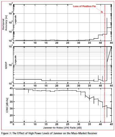
Figure 7 neatly summarises the results obtained with the mass-market receiver. The receiver lost position fix when the J/N ratio reached 43dB. After this point, horizontal positioning accuracies worsened rapidly up to 1500m. Positioning accuracy had worsened before positioning capability was lost, but only reached about 5m error before failing, i.e. the receiver “knew” that it had lost positioning capability when the output error level was about 5m. It continued to output a propagated position estimate, the accuracy of which degraded rapidly. Geometric Dilution of Precision (GDOP) rose and average C/ N0 (Average C/N0 is based on the number of available satellites to the receiver. For example, if the receiver is tracking a single satellite with a C/N0 of 35dBHz, that figure was considered to be the average C/N0 for the receiver.) dropped as interference power was increased. These findings were as expected. Broadly similar findings were made with the survey grade receiver, and are not reproduced here.
These tests showed that the particular receivers tested had a high degree of robustness to interference at a distance, but that high power interference, caused by either close proximity to a jammer or potentially to a higher-powered interference source, would cause service denial.
Generally GNSS receivers do not alert users of interference, even when this degrades or inhibits receiver performance. Instead interference may cause either (a) the receiver output (position or time) to become unavailable, (b) the output to freeze at its previous value, (c) the output to become unreliable (propagated solution, unconstrained solution, potentially hazardously misleading information). The impact of interference on equipment, applications, and services for which GNSS receivers provide position or timing inputs depend on the implementation of those complex systems and services. The lack of GNSS receiver problem alerting is likely to cause consequent equipment, applications, and service problems that are beyond the scope of the present work.
Conclusions
Several conclusions can be drawn from the GEMNet project:
1) Clear evidence of GNSS interference was collected. During 100 observation days, between 600 and 1800 interference events were captured over four sites. The variation in number of observations was due to the different sensitivities of the two different detectors used. This confirms that a potential threat exists to the operations of GNSS users in the United Kingdom.
2) Interference observed was of very low power, with the majority less than 5 dB jammer to noise (J/N) ratio. This is consistent with low-power (less than a few milliwatts) jammers on the roads that were typically 100m or so from the GEMNet GEMSS sites.
3) Very occasional higher interference power (J/N of up to 25 dB) was observed. This is consistent with very occasional close approach (perhaps 10 metres) of a lowpower jammer to a GEMSS site.
4) Much of the interference observed had radio characteristics (spectrogram and power level, temporal characteristics) consistent with deliberate (lowpower) jamming, produced by devices commonly referred to as PPDs (Personal Protection Devices, or equivalently in-car jammers). Some interference had characteristics that may have been accidental low-power emissions from devices other than jammers. Some interference was of such low power that it was not possible to extract sufficient power above background noise to assess whether it was distant low-power jamming or accidental interference.
5) Building on one of the gaps from previous studies by other researchers, the GEMNet Network collocated a mass market GNSS receiver and a survey-grade GNSS receiver with the interference detection sensors at each of the GEMNet sites.
6) In most cases there was no discernible degradation in GNSS receiver (neither survey grade receiver nor mass market receiver) performance despite detection of interference by the sensors. This is consistent with the commonly reported observation at many sites that, although interference may exist, it generally does not lead to service outage or other problems.
7) In the worst cases, GNSS receivers collocated with the GEMNet interference sensors were marginally affected by interference. This included marginal (cm-level) accuracy changes in the massmarket receiver; no accuracy degradation was observed in the survey grade receiver.
8 ) If separations between the interferers and operational GNSS receivers were less, or if higher power interferers started to appear, then the risk would be larger. This could potentially cause a receiver to lose its ability to position reliably. This unreliability could manifest itself as HMI (hazardously misleading information) or denial (loss of positioning).
9) An important second part of the GEMNet work was to replay the captured interference profile at a higher power than observed in the field, under laboratory conditions, and to examine the impact. This part of the study showed that the mass market receiver suffered no significant adverse effect from interference below a jammer to noise ratio (J/N) of about 35 dB. It lost lock and was unable to track satellites at a J/N of about 43 dB. The survey grade receiver was robust to about 33 dB jammer to noise ratio. It lost lock and was unable to track satellites at a J/N of about 39 dB. Should operational jammers with 1000 times higher power than those operating today become common, then both mass market and survey grade GNSS receivers could often be compromised.
10) Low-power jammers (with powers similar to today’s levels) can under some circumstances approach to within much closer distances to GNSS receivers at CNI sites. Indeed at many CNI sites there is nothing to stop close approach of such jammers, nothing to detect their presence, and no mechanism to dissuade this from happening, even though transmissions from such jammers are nominally illegal (It is an offence under the 2006 Wireless Telegraphy Act to emit radio signals in the GPS L1 frequency spectrum (or at other GNSS frequencies). The enforcement of this Act against low power (PPD-type) jammers is at best weak in the United Kingdom and elsewhere). For the GEMNet work, the distances between the GNSS receivers and nearby roadways was typically 100 to 150 m. A simple radio propagation calculation shows that 30 dB higher power would occur with such a jammer brought to about 5 m from the CNI GNSS receiver. Such a distance is approximately the nominal range of a PPD-type jammer.
Recommendations
Several recommendations are made based on the GEMNet work:
1. Expand GEMNet-like GNSS threat monitoring to cover multiple locations and extend monitoring over a protracted period of time, in order to create a comprehensive database of up-to-date threats, against which to assess potential user impact.
a. This could usefully be coordinated at National level since the threats experienced are likely to be common across multiple commercial and governmental sectors.
b. This could also be usefully coordinated internationally since threats experienced are likely to be common across many nations.
2. Standardise GNSS threat recording data parameters nationally and internationally, so that threat characteristics can be captured by platforms and detectors provided by multiple commercial vendors. This will facilitate exchange of information on new and emerging threats across multiple states, thereby highlighting any particular concerns as well as supporting early development of threat mitigation mechanisms.
3. Assess, and create a database of, the impact of identified interference threats on commercially available GNSS receivers. This might, for example, be undertaken by replaying the threats through an appropriately configured Radio Frequency Simulator as was done for the GEMNet work. This will allows users to accurately assess their risk based on the receivers that they use, will support investment decisions for those who rely on GNSS equipment performance, for example for critical infrastructure – i.e. ability to procure GNSS receivers capable of mitigating known threats. In addition this will support improvements in receiver and antenna technologies and augmentations since many mitigation capabilities already exist within the industry, but without an appropriate threat definition the market demand is weak.
4. Create a set of draft minimum performance standards for robust GNSS receivers (i.e. receivers that can mitigate identified operational threats), and in parallel propose performance test methodologies and specifications. Such standards and tests will probably be domain specific because of the diversity of involved bodies; however substantial elements will also be common across multiple domains since the GNSS signals are common; as are many of the threats and vulnerabilities.
5. Extend the work undertaken thus far to encompass other threats to PNT operation, such as atmospheric effects / space weather, and radionavigation spoofing.
6. Examine threats to the radio spectrum at other frequencies where radionavigation systems are implemented or proposed in order to more robustly understand potential threats to such systems. This might usefully include other GNSS frequencies or ground based radionavigation signals
Acknowledgements
This work was undertaken jointly by the Satellite Applications Catapult and Ordnance Survey. The execututive management of both organisations are thanked for permission to publish. The views expressed are those of the authors and do not necessarily reflect policy of the Satellite Applications Catapult Ltd or Ordnance Survey Ltd.
The assessment of the state of the art was based on published material, drawn from a number of openly published sources. This aspect of the work was assisted by helpful insights from a number of experts in the domain. We would like to express particular thanks to experts from the following organisations: Chemring (Roke Manor), InnovateUK, Nottingham Scientific Limited (NSL), Spirent Comunications plc, and the Universities of Nottingham, Westminster, and Imperial College.


 (85 votes, average: 2.36 out of 5)


Leave your response!