| GNSS | |
An analytical assessment of a GNSS-based train integrity solution
This paper deals with the use of the GNSS to monitor the train length and to estimate the position where the last carriage of a decoupled train is stopped |
 |
|
 |
|
 |
|
The signaling system plays one of the most important roles in railway applications. In fact this segment is not only responsible for providing safety, but it has also in charge the traffic management. This entity has two main tasks: provide safety by reducing the probability of accidents due to human error and manage railway operations by increasing the efficiency of the lines [1].
In order to guarantee interoperability between national networks, the standard ERTMS/ETCS (European Railway Traffic Management System/European Train Control System) has been developed; in fact, beside ERTMS there are more than 20 train control systems across the European Union and each train used by a national rail company has to be equipped with at least one system but sometimes more, just to be able to run safely within that one country as in [2]. This means that generally it is an hard task to manage the cross-border traffic. In this sense, having a unique standard can provide interoperability and increase the freight and passenger transport across the European countries. Furthermore the ERTMS standard has been adopted by other countries outside the Europe.
Within the ERTMS, three different application layers, known respectively as L1, L2 and L3 level, can be identified. While L1 and L2 are already in operation, L3 has not been implemented yet, but it represents the next frontier for improving the ERTMS performance. Figure 1 shows the three operational levels.ERTMS L1 has been designed to operate on conventional lines already equipped with traditional trackside signals and track circuits. In this level, communications between the devices deployed in the track area and the train are provided by means of dedicated balises (known as “Eurobalises®”). These devices are usually located adjacent to the lineside signals and connected to the train control centre. The onboard equipment, by receiving the Movement Authority (MA) through the balises and knowing the train characteristics, is able to evaluate the maximum speed and the next braking point. These data are shown to the driver through a dedicated display called DMI (Driver Machine Interface). However, the train speed is continuously monitored by the ETCS onboard equipment and, if the speed exceeds the one stated by the Moving Authority, the train will be automatically stopped. Despite L1 increase substantially the safety level and the interoperability between the railway signaling systems, the original solution has not an high efficiency. Let us look at this exemplum: the train has received a Moving Authority that states that next signal is red and so the driver expecting to stop the train before the signal reducing the speed; in the meanwhile the signal has come to green but the driver doesn’t know this event until he has the signal in sight. This means that he can’t increase the speed until the train catches a new balise obtaining the new moving authority. To mitigate such an issue, it has been designed the infill technique in order to earlier notify to the train the signal changing event.
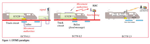
In the more advanced phase, called ERTMS L2, the Movement Authorities are sent directly from a Radio Block Centre (RBC) to the onboard unit using the GSM-R (Global System for Mobile Communications – Railway) technology. In this level, the balises transmit only “fix messages” containing information about the line. A continuous data-stream notify to the driver of line-specific data and signals status on the route ahead; in this way the train is able to reach the optimal speed guaranteeing a safe braking distance factor. By using L2, it is possible to reduce maintenance costs (e.g. fewer lineside signals) and increase the capacity of the line.
The main limitation in the traffic management efficiency of L1 and L2 technologies is the “fixed block” approach used to determine which portion of the line is occupied by a train. In fact, the line is split in several sections, called blocks, of predefined length; the main idea is that one block can be occupied by no more than one train at the same time. To determine whether a section is occupied, the system makes use of Track Circuits deployed along the track.
This solution, despite it guarantees an high level of safety, is expensive (in terms of device to be deployed and of maintenance costs) and does not guarantee an efficient use of the railway network. If we were able to allocate the block dynamically, we would increase considerably the capacity of the line. This new concept known as the “moving block” approach is the mainstay of the future phase of the ETCS called L3. In L3, it is the train that has in charge of supply continuous and accurate position data to the control centre; in this way the track based detection equipment are not needed anymore. The absence of physical track circuits is one of the things that allows the “moving block” approach; in fact, if we wanted to reduce the section length (e.g. assuming that the section is as long as the train itself) we have to define a Virtual version of them. In [3] authors referred to this concept as the “Virtual Track Circuit”.
The control center, to dynamically determine the required safe distance among adjacent trains, needs that the trains report their locations and their actual length. In fact, rarely, it could happen that a section of the train decouples from the rest of the train; in these cases, the real train length (that is the one we need to evaluate the occupied section) is bigger than the nominal one. We refer to train integrity as the ability of the train to determine whether all the carriages are still coupled each others. This implies the needing of a train integrity subsystem that has to measure and trust the train length (with a given probability of success) and to alert (within a time limit) if a portion of the train is decoupled, assessing the length of the line occupied by the train. All this process must be compliant with the CENELEC SIL-4 high level requirements (Tolerable Hazards Rate < 10-9/hour). To assess the train integrity issue, several solutions have been proposed. In [4] authors have envisaged a Train Integrity Monitoring System (TIMS) which relies on hardware equipments deployed on each coach interconnected through serial links. If a carriage loss occurs the Master device in the front of the train is no longer able to communicate with the lost ones. In [5] authors provide a freight train integrity monitoring approach based on a distributed WSN (Wireless Sensor Network) that check real-time the train composition. The main concept is that a carriage loss implies that the train configuration is changed. The main disadvantages of this techniques are the deployment of hardware devices in every carriage and the link establishment between all of them. In the last years, other solutions based on GNSS technology have been proposed addressing the train integrity problem, but, anyway, those solutions have not been proved to be compliant with the SIL-4 stringent requirements. Recently in the USA, Leidos presented a PTL (Positive Train Location system) to fulfill the requirements of the PTC (Positive Train Control) through the data fusion between several sensors including GNSS [6]. However for none of these solutions has been provided the demonstration of meeting the Tolerable Hazard Rate (THR) specified by over mentioned CENELEC norms. In [3] authors defined a GNSS double difference approach to assess the train integrity issue. This approach, despite the double chain GNSS need, is able not only to detect if a decoupling event has occurred, but can be also suitable for the localization of the rear section left on the line; in fact, thanks to the receiver in the last carriage, we can perform a PVT (Position Velocity and Time) estimation and notify the actual location of the lost rolling stock. In such a way the traffic management system can calculate the safe distance that the preceding train must respect to avoid the collision. Further to the results of their research, in this paper we investigate the achievable performance of a multi-constellation GNSS-based train integrity system to contribute to the integrity function envisaged for the ERTMS L3. Finally we carry out simulations to assess the analytical model.
Problem statement
As announced in the previous section, the Train Integrity Issue is one of the mainstay problems still to be solve. In fact, even if it is possible, for those trains with a fixed composition, to identify the decoupling by the break of a wire connection linking all the carriages, there is an uncertainty on the final position reached by the parted rolling stock. This happens because the RBC (Radio Block Centre), even if it knew the train position and velocity at the decoupling moment, the breaking distance, that changes with other external variables (such as the track gradient, the track wetness, the train weight, the brakes type, and so on), could not be evaluated with precision. In such a way, the portion of track that must be reserved as guard interval has to be increased to prevent possible collisions with the following convoys. For the variable configuration trains the same consideration can be done by using the pneumatic pipe; if there is a depressurization on the pipe the train is parted in more than one piece. The problem of such an approach is that not always the pressure drop in the duct is as much high to be detected as a decoupling event (this means that the lost rolling stock will be braked while the front section will continue its running as if nothing was really occurred).
More in details, the on-board train control unit notifies the decoupling event to the RBC with an estimated latency between the 10 and the 20 seconds; this means that for a train travelling at 120 km/h, the decoupling point is in a range of about 700 meters (conservative hypothesis). Then 750 meters (plus a conservative margin of 20%) should be taken into account to estimate the position where the last carriage is stopped. Further uncertainty arises in presence of a height gradient along the line. In fact the breaking distance varies when the train is going uphill or downhill and a further margin has to be calculated to estimate the position where the last carriage is stopped.
Our proposed approach, by means of a pair of GNSS receivers located in the extremities of the train, will overpass this issue by assessing the train length during the operational phase (when the carriages are all coupled each others) and by providing directly the position of both head and end cars.
Proposed approach
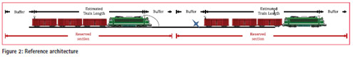
Let us consider a railway scenario as depicted in Figure 2. If N is the number of available constellations, we have two possible approaches: N out of N or the all in view satellites. The former foresees that the train length is estimated N times by using one constellation at once; finally, if one of them exceeds a certain threshold, than an alert is arisen. The second method is based on a merged constellation approach; in fact we are considering all the visible satellites like they belong to a unique virtual constellation. For the train length estimation algorithm for a single constellation we remand to [3].
To set the threshold in case of the use of all in view satellites we can adopt the Neyman-Pearson criterion, then imposing the target False Alarm probability. The main advantage of the joint use of the visible satellites is the higher accuracy that can be achieved by combing all available measurements with the optimal weights. On the other hand, when using the N out of N approach we have the possibility to optimize the threshold for each constellation. Furthermore, when the statistics of one constellation exceeds the threshold, a second test can be performed to identify the presence of a satellite or even a constellation fault.
For instance, let first consider the case of two constellations. In this case, if Pfa is the required False Alarm probability, then we can write:
![]()
If the required False Alarm probability is low (typically in the order of 10–6 or lower), the mixed term is several order lower than the others; so, neglecting this term, we can equally subdivide the false alarm probability between the two detectors. For a given False Alarm Probability the threshold is proportional to the standard deviation of the tested statistics. We can generalize this concept to the use of N constellations. Thus, considering that
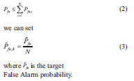
As shown in [3], under the hypothesis of additive Gaussian GNSS receiver noise, the train length estimation error is zero mean Gaussian distributed. This means that for each constellation we can evaluate the threshold by simply inverting an erfc function. To evaluate the standard deviation of the distribution we need an on-field tuning that is function of the nominal baseline length. Under this hypothesis, the False Alarm probability can be written as:
Given the threshold we can evaluate the detection probability. In presence of a decoupling event, the train length will be greater than the nominal value. Because, obviously, the actual train length is unknown, we can consider the distribution obtained comparing the estimated train length with the nominal one. In the instants immediately after the decoupling event, such distribution, for
The total miss detection probability can be computed by considering that the decoupling event is not detected if none of the single constellation detectors is able to detect it. Due to the statistical independence between the estimation errors we have:
Simulation results
To assess the performance analysis of the over mentioned model, we carried out simulations on a synthetic scenario. More in details, we considered two trains: one passenger train length 500 meters and one heavy freight train 2500 meters long; both trains were running, with a speed of 80 km/h, on a track from “Roma Tuscolana” station to “Zagarolo” station (Rome, Italy) as shown in Figure 3.
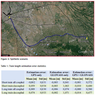
As in [3] we adopted the conservative approach by assuming that, after the decoupling, the rear section of the train slows down only by effect of the rolling resistance while the front section continues the running as if nothing has occurred. Moreover, the gravity effect due to the track gradient has been neglected too. The train length estimation is then performed by using three SIS (Signal In Space) configurations: only GPS, only GLONASS and GPS+GLONASS. In Table 1 we report the estimation error statistics. As expected by using a multi-constellation approach the standard deviation of the estimation error reduces by means of the higher number of visible satellites. Furthermore, because after the decoupling the front section continues its running, the standard deviation of the estimation error increases (at the end of the running the baseline between the receivers is about 30 km).
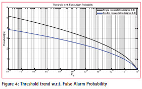
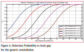
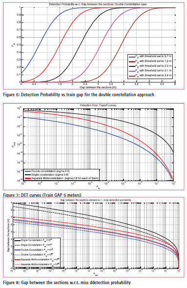
Figure 4 depicts the trend of the decision threshold w.r.t. False Alarm Probability. The trend is reported for both Single Constellation and the satellite all in view case. As expected by using the Double constellation approach, when all the satellites are healthy, we reduce the standard deviation of the estimation error; by effect of this, for a given false alarm probability, we have a lower threshold. Figure 5 and Figure 6 show the trend of the detection probability w.r.t. the gap between the decoupled carriages for several thresholds values respectively for the single and double constellation cases. As expected, the Detection Probability is equal to 50% when the gap is equal to the selected threshold and the lower is the threshold, the higher is the detection probability for a certain gap. Figure 7 shows the Detection Error Tradeoff curves for a Train GAP of 5 meters in the case of healthiness of all the involved satellite. Obviously, when there are neither satellite nor constellation faults, the all in view satellite combination represents the best alternative. However, with the performance are higher than in the single constellation case and we can adopt a secondary screening when the estimations disagree to eventually exclude the faulty satellites or constellations.
Figure 8 depicts the gap that can be protected for a given miss detection probability. As expected the lowest is the miss detection probability we select, the higher is the interval we have to reserve.
Discussion of the results
The analytical modellisation is a basis to assess the performance achievable by selecting the different parameters. Analyzing Figure 8, it is possible to derive, in terms of protected gap, the confidence interval to be considered when reserving the section of line. More in details, if we select a false alarm probability equal to 10–4 and a miss detection probability equal to 10–9, we have to consider a tail buffer of about 8 meters with a single GNSS constellation
Instead, if we adopt the 2 out of 2 decision-approach, we have to allocate a tail buffer of about 6.5 meters. The shortest tail buffer is achievable with the double constellation approach, and it is in the order of 6 meters. Therefore the theoretical maximum length of the virtual block will be 12 meter longer than the nominal train length. While the position where the last carriage is stopped depends on the confidence error estimated by the localizer that can be as low as about 14 meters with a dual constellation system [7]. It is important to remark that these results do not take into consideration the impact of the multipath effect and the mitigation techniques that are being investigated in the continuation of this study.
Conclusion
The train integrity monitoring represents a fundamental innovation for the train control systems such as the ETCS L3 system. GNSS is the candidate technology to allow the continuous monitoring of the train length and for estimating the position where the last carriage of a decoupled train is stopped. This paper has provided the analytical results of the GNSS technique in order to assess the achievable performance. Further studies are on-going to characterize the environmental effects, but the advantages of the GNSS have emerged when compared to other solutions.
References
[1] A. Neri, A. Filip, F. Rispoli, and A.M. Vegni, “An Analytical Evaluation for Hazardous Failure Rate in a Satellite-based Train Positioning System with reference to the ERTMS Train Control Systems”, ION GNSS 2012, Nashville, TN, U.S.A.
[2] http://www.ertms.net/?page_id=40.
[3] A. Neri, F. Rispoli, P. Salvatori, and A.M. Vegni, “A Train Integrity Solution based on GNSS Double- Difference Approach”, ION GNSS+ 2014, Tampa, FL, U.S.A.
[4] S. Oh, Y. Yoon, K. Kim, and Y. Kim, “Design of Train Integrity Monitoring System for Radio based Train Control System,” Control, Automation and Systems (ICCAS), 2012 12th International Conference on , vol., no., pp.1237,1240, 17- 21 Oct. 2012, Jeju Island, Korea.
[5] H. Scholten, R. Westenberg, M. Schoemaker, “Sensing Train Integrity,” Sensors, 2009 IEEE , vol., no., pp.669,674, 25-28 Oct. 2009
[6] K. M. Betts, T.J. Mitchell, D.L. Reed, S. Sloat, D.P. Stranghoener, and J.D. Wetherbee, “Development and Operational Testing of a Sub-meter Positive Train Localization System,” IEEE/ION PLANS 2014, Monterey, CA, May 2014, pp. 452-461.
[7] F Rispoli, Aleš Filip,M. Castorina,Gino Di Mambro,Alessandro Neri,Fabio Senesi. “Recent Progress in Application of GNSS and Advanced Communications for Railway Signaling”. 23th Conference Radioelektronika 2013, April 16- 17, Pardubice, Czech Republic


 (1 votes, average: 4.00 out of 5)


Leave your response!