| GNSS, TIME | |
Synchronet – an innovative system
|
||||
| A central issue in designing complex networked systems for critical applicative domains is the possibility of keeping each node of the network synchronized with respect to a given system time scale. The problem is even more critical when the synchronization accuracy determines directly the performances of the whole system. In this paper a distributed synchronization infrastructure is proposed providing: • high accuracy synchronization performances (nano and pico seconds) • flexible and scalable service topology (up to global scale) • ease of integration in preexistent infrastructures • ease of customization, both at user level and at system level, in terms of performances and security. IntroductionHigh performance synchronization is a fundamental feature in many applicative domains, in particular it may be directly bounded to: SynchroNet is an innovative system, patented by Thales Alenia Space Italia, that aims to be the sole solution for every application type which needs an highaccurate synchronization covering all levels of performance and coverage requirements with the added value of the ease of integration also in preexistent infrastructures and systems. Therefore, SynchroNet is able to cover, with a complete, flexible and high-performance product, the synchronization needs of a wide range Gnss Based SynchronizationIn metrology, the synchronization of two clocks is the process required to determine the relative behavior of one clock with respect to the other. In particular clock synchronization can be defined as the process required to compute at least two parameters: time offset and time drift. Time offset is the relative, instantaneous, difference between the two time scales (i.e. the phase offset) divergence trend of the two clocks (i.e. the frequency offset). It should be noted that, if the relative behavior of the two clocks is known, they can be considered synchronized even if no physical adjustment is carried out. While synchronizing two co-located clocks could be as easy as measuring 1PPS offsets over time by mean of an accurate Time Interval Counter (TIC), synchronizing several kilometers away clocks with nanosecond accuracy and precision performances |
||||
Franco Gottifredi, Monica Gotta, Enrico Varriale, Daniele Cretoni
|
||||
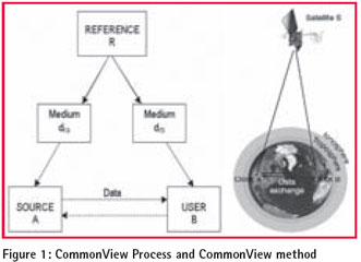
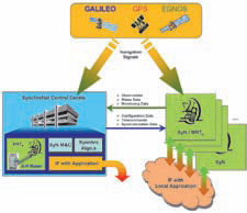
| To solve this problem GNSS based techniques have been preferred over other methods for many reasons, among which: • availability of the GNSS navigation signals • performances • diagnostic information about GNSS system health. GNSS based synchronization could be carried out by mean of the CommonView technique which exploits navigation signals broadcasted by GNSS SVs (Space Vehicles) which are in a condition of “common view” from the observation points of the two sites to synchronize. Figure 3: SynchroNet network topology A schematic representation of this method and the related process is The CommonView method is very simple in its theoretical formulation From the sketch above, can be identified at least two such issues: Delays to be compensated are mainly due to the propagation in the atmosphere (i.e. Ionosphere and Troposphere). For each segment a delay factor is computed using mathematical models. The residuals of delay corrections are among the limiting factors for the Common View While Delays affect only the synchronization computation, Data Exchange affects, also, other aspects that system designers have to take into account: Synchronet Overview SynchroNet is a distributed approach to synchronization with centralised monitoring and control facilities (see Figure 2). To provide a synchronization system that deals with all issues described in the previous paragraph, SynchroNet implements a networked infrastructure around the core time transfer algorithms and distributes the synchronization process over a hierarchic network with hierarchic network nodes roles. This approach allows to distribute and keep balanced the processing load and limits the propagation of failures. In the SynchroNet system three kinds of nodes are present: Figure 3 provide an overview of the SynchroNet network topology The Control Centre provides centralised monitoring of each node of the network in terms of equipment health status, connection link and security and synchronization performances. The CC is also responsible for network management allowing the supervisor to change the network topology (add a new node, remove a node, assign a node to a Figure 4: Preliminary analysis tool for optimal baseline determination Figure 5: Number of satellites in common view for different baselines MRTs are the distributed time references and form the hierarchic synchronization backbone of the system. Each MRT computes synchronization of the allocated SyNs and receives the synchronization SyNs are the leaves of the graph representing the SynchroNet network; SynchroNet is characterized, at each level, by a strong modularity of its Each SynchroNet node can be seen as a functional logical entity composed by many sub modules interacting with each other by mean of well defined interfaces and protocols; this means that a single node deployment may span many physical/ virtual machines. Each sub module is well defined in terms of pre and post conditions and |
||||
Franco Gottifredi, Monica Gotta, Enrico Varriale, Daniele Cretoni
|
||||
| Inter-nodes data exchange is guarded by Networking Module which applies a second, packet level, encryption and crypto signature to the outbound data before routing information through the SynchroNet VPN.
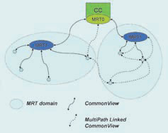
Additionally, each node provides synchronization interfaces by exporting synchronization products in many different ways, for example: These products are exposed through standard interfaces (i.e. standard analog frequency and PPS signals, filesystem objects or TCP/IP based connections); this approach is consistent with the modular nature of the system and allows SynchroNet to be regarded as an higher level service providing black box, entirely defined by its interfaces. This design allows the easiest integration of SynchroNet in pre-existent infrastructures and permits effective maintenance cycles. Figure 6: LCVTT technique Synchronet Distributed SynchronizationThe choice to design a distributed commonview based synchronization In particular one of the main design goals was to have a system that could be able to scale to an arbitrary service coverage area without requiring recurrent upgrades due to the increased load of servers and network equipment and that could cope with some limitations of the CommonView and Linked CommonView synchronization techniques. By running both short term and long term performance analysis of Common View algorithms exploiting the IGS (International GNSS Service) network was found that a minimum optimal number of satellites in common view is five. Again processing GPS almanac data and cross correlating with IGS stations network was found that a direct For longer baselines the LCVTT (Linked Common View Time Transfer) approach should be applied. A generalization of the LCVTT technique is represented in Figure 6 Synchronization between station A and C is carried out by computing ΔT(A,C) = ΔT(A,B) – ΔT(B,C) Figure 7: SynchroNet distributed synchronization process The first improvement given by wrapping synchronization into a dedicated homogenous network is the ability to distribute the computational process. Each node (which is guaranteed to be, at nominal conditions, not farther than 6000Km from its direct reference station) sends collected GNSS data to its reference node (MRT) and receives back synchronization products (clock model, synchronization noise, synchronization propagation errors, stability statistics and a summarizing synchronization integrity indicator). The synchronization loop is depicted in Figure 7 for a three level depth network. Each MRT is in charge of computing the synchronization and the detailed monitoring parameters only of lower level SyNs and MRTs; furthermore a status report is sent to the Control Centre. This architecture allows a higher level of customization both of the network topology and of the synchronization process. Network, by mean of data meta-routing (implemented at the Data server module) which allows information being routed to multiple destination, may have, for example, multiple Control Centers (a Control hierarchy could be implemented to face network growth just as pagingand indirect indexing methods works for computers operating systems). This flexibility allows a different approach to Multi path Linked CommonView that can be realized by sending observables data to different, higher level MRTs. The CC defines, when nodes join the network, the path set for MPLCVTT by knowing the detailed status of each node already in the network and their performances; paths can be recomputed when events happen: nodes moved, added, removed, status change (synchronization performances, link, observables quality, …). Figure 8: SynchroNet runtime fault recovery SynchroNet, not only provides a configurable and customizable synchronization network but allows a runtime automated or semi-automated network reconfiguration capability. In particular SynchroNet can take automatic actions in case an MRT goes down by reallocating the whole branch under the failing node. An example is given in Figure 8. All the configuration steps are carried out by the main Control Centre which is, in general, the only authority able to modify the network topology (add, move, remove and fully configure a node). In particular each node is connected to the Control Center by a dedicated VPN which is separated by the network used for data exchange between other network nodes. |
||||
Franco Gottifredi, Monica Gotta, Enrico Varriale, Daniele Cretoni
|
|||||||||||||||||||||||||||||||||||||||||
Implementation and Test ResultsThe main issue is the validation of SynchroNet core synchronization algorithms in their many components: ionospheric and tropospheric models implementation, code (i.e. pseudorange: Code and Phase) based CommonView, phase based CommonView (L1 and L2), clock stability characterization by mean of CV and comparison to direct synchronization in lab (PPS biases analysis). IGS was selected as a test bench for algorithms validation thanks to the Here after are presented some results of both validation test results and of performance assessment of SynchroNet algorithms. SynchroNet is at its v1.0 verification phase but its kernel is already running as core service for the Galileo Test Range (GTR), an advanced research facility for the experimentation and analysis of the Galileo Signal, for testing and certification of user terminals and support services for the development of application services. In the frame of this project, SynchroNet is used for synchronization of pseudo satellites ConclusionsSynchroNet is a GNSS based time and frequency transfer System that Through separated and successful validation campaigns using IGS network and in a full deployed system (the GALILEO Test Range), SynchroNet has proven its customizability and performances. Currently SynchroNet is going through a further design and research BibliographyD. W. Allan, M. 1) A. Weiss, “Accurate Time and Frequency Transfer During Common-View of a GPS Satellite”, 34th Annual Frequency Control Symposium, pp. 334-346, May 1980. |
|||||||||||||||||||||||||||||||||||||||||
|
|||||||||||||||||||||||||||||||||||||||||
|


 (No Ratings Yet)


Leave your response!